29 noiembrie 2018

File Transfer using DMR SmartPTT File transfer

For our needs of file transfer on Emergency Communications we often need some independent and autonomous solution to transfer files over the radio.

Because we are intense users of DMR with Motorola infrastructure (DR3000 repeaters connected with SmartPTT from ElcomPlus), we were interested to use the same infrastructure for file transfer.

Therefore  as the first choice, we came to SmartPTT File Transfer freeware from the same ElcomPlus.

The second choice is to use the SmartPTT RadioServer, which is the paid solution.

On the internet are some discussions about this but the guys have mixed emotions about this solution.

After some intense tweaking and testing in the real world,  we came to conclusion that the Help file of the freeware is somehow insufficient to obtain consistent results.

Short story,  in order to make the SmartPTT File Transfer to work you will need one radio to be defined as "SERVER". This will be the receiving side of the system.
We assumed that this radio will use the ID 2263002.

Short digression:
By using this online IP conversion tool, we transform the SID 2263002 to IP: 0.34.135.218.
Because, in the ham network we are all using CAI 12 (First octet) we will substitute the "0" with... "13"! Yes, that's right, Motorola add 1 to the CAI to obtain the first octet! 
This is to be found in the MotoTRBO System planner in an obscure note :-) but if you want to know more, i strongly recommend you to read this.

So, the IP address of the radio interface of the Server radio is 13.34.135.218.

For the test radio I wanted to taste a range of ID's, from 2260000 to 2269999. So, we will have a range of IP's from 13.34.124.32 to 13.34.163.47. In network terms, we can define the range as 13.34.0.0 with mask 255.255.0.0. This will be needed further, when we will set the route in the routing table.

1. Setting up the radios. 
-Both of them have to use a common Talkgroup for file transfer.
-Both radios are connected to a corresponding computer via USB cable.
-On BOTH RADIOS, define a channel in the CPS and check for the following:

TX Preamble

 We are using the default IP for the Network adapter on the PC side and the PDU size=500:


Uncheck "Data call confirmed":


2. Adding the radio interfaces to routing table.
This is delicate. On the server PC (receiving side) we have to add a range of radios IPs. On the Client PC (the sender), we can add only the sending radio IP. But, for the sake of testing, I added the whole range to both computers used in the experiment.

To add the routing table, we have to start CMD in Administrator mode. This is important to the next step because if you don't do it so, you will not be able to save the new routes.


After you open the CMD window, you will have to put the route calculated for your network with the following line:

                       Radio IP Range                                 Gateway Radio IP
route add -p xxx.xxx.xxx.xxx mask 255.255.0.0 192.168.10.1

"Radio IP Range" will be calculated as shown above.
"Gateway radio IP" is the IP of the USB interface of the radio connected to the PC.

3. Setting up the Client and Server.

To simplify the things, I am showing here both pieces of software ready to be fired up.
On the Client you have to set the ServerID which is 2263002.
On the Server side, you have to open the Settings and add the Client radios. This set the permission to accept file transfer from that particular ID's.


That is all you need, go test it!

How we use this?
We defined the destination folder for transmitted files in an OneDrive folder in the Microsoft Office365 platform we are using. Therefore, after receiving it, the file is available online for all our team.


Of course, there is a posibillity to send files directly to a SmartPTT RadioServer but this will be our little dirty secret!

Thanks to ElcomPlus for supporting RVSU, the Romanian Radioamateurs Emergency Network!

73


06 octombrie 2018

New QRP-uBITX in the shack - III - Transmitter section mods

OK, it was the time to see how the TX section of the uBITX is...


From time to time I also tested how it fits inside the case...
The radio PCB was fixed on a larger one-side plated PCB that slides into the aluminium case.

I also checked the front panel to see if the potentiometers and other stuff are OK with the main board...


First of all, the Tx power was around 7-8 W PEP on 80 and 40 m bands, decreasing to around 2W on the higher frequencies.


First tought was to fiddle aronud with the IRF transistors... I was eager to try to change them with RD16HHF1...

So, I changed them (sorry, have no pictures about this :-( ) and also changed the T11 with one 1:2 made on a BN61-202 core (I am not sure about the size but the ferrite mix is definetly a "61" type).

I noticed that the C261 and C202 was missing.... What???  Yeap, they was missing!
So, I changed the R261/R262 with 1kOhm and put there two capacitors of 1nF.
Also set the drain current to about 250 mA for each transistor.

The results was not able to convince me... The transistors ran hot, too hot and the Tx power was about the same.

So, I reverted back to IRF510, kept the new transformer. I kept the neutralisation network as described above and put a 27 pF between the Draines of Q94 and Q95.

The Drain current was set at 150mA each.

I removed the original transistors Q90, Q911, Q912, Q92, Q93, Q96 and Q97 (2n3904) and put some female pins instead to play with other transistors.

I have a lot of BFW17 and BLW65 and by looking at the datasheets, I choose BFW17.

I masured the transistors to have identical hFE and I choose one with 120 for the Q90 and the rest of them was with hFE of 92.

I added some 33Ohm resistors (paralleled) on the R87, R88, R911, R96, R941 and R942.

After this mods, I fired up the Tx answering to some CQ's and the power-meter showed about 12-17 W PEP on all range (1.8 MHz - 29 MHz).

I still had to put it on the Spectrum analyser and do the two tone test...

You can see two RG317 wires. Those are to put the final stage to test on the Spectrum analyser with tracking generator to see what is the effect of the mods I made on the PA.


Again, testing if it fits inside...


Here you can see the new output transformer and the PARF radiator.


Also, on the Raduino board (which will have it's own story), you can see a big 0,45 Ohm/3W resistor in series with the LM7805 input.


At the RF output, a 1:1 choke balun was made from the RG317 on a 43 mix toroid and a gas discharge protection was added.


01 octombrie 2018

New QRP-uBITX in the shack - II - A few necessary measures

First of all, the board is "Rev 4" which means it came with discrete audio PA and "Audio pop mod".


We'll get back later to this diagram.


1. After unpacking, the parallel LCD was replaced with a I2C one as I want to free some hardware resources for further improvements.
I uploaded the new firmware, the one from KD8CEC. 

A quick test for the Raduino board. Everything is OK.


2. The crystal ladder filter must be grounded. A small 0.8mm hole was made and a ground wire soldered on all crystal's cases.
I used the occasion to implement the mod for the variable IF filter.
For that, I removed C217, C218, C219, C220 and C221 and replaced with 5 varactor diodes.
I found SVC236-TB-E to be suitable for this purpose as I need to have between 50-100 pF and a good stability over a large temperature range.


Here it is how it looks... You cannot see the varactor diodes here because of the 47k resistors but they are behind the line of resistors, right in the place of the removed capacitors.


Here is the diagram for the mod.


A few words about:
-The Rx and Tx are 12V from the K1 relay. I took the voltage from R48 and R38. 
-The 12V which came from the Rx/Tx relay are regulated by the two linear regulators. As we increase the voltage, the IF bandwith widens. For Rx, 0 to 8V measured at the common cathodes of D6 and D7 correspond to a variable bandwith from approx 250 Hz to 4 kHz. For Tx, a voltage around 2.9V gave a nice warm modulation of about 2.8 kHz.

I have on the panel only P1. You can use any linear regulator or even some Zenner diodes with 4k7 resistors.

The components are placed on a small universal PCB. The components are not critical.


3. Some mods are necessary also on the audio PA stage.
There are some crossover distorsions that made the audio bad. To solve them, I modified the polarisation of the final transistors. Remember I told you we will revisit the schematics of the audio PA? Good! Between D15 and D16 a resistor must be inserted. I tested various values and the best results was with  10 Ohm. The trace between the two diodes was cut and the SMD resistor was placed right between.


Here it is how IF variable bandwith sound (CW):


I also use this TRX to listen to MW broadcast:


........ more to come!


30 septembrie 2018

New QRP-uBITX in the shack - I - Welcome preparations

A while ago, a friend asked me to fix his uBITX.
I started to search information about this little radio and found amazed that is very close to what I proposed myself to make! So close that the IF are the same to my personal project!

So, after I fix that radio and test it I was very impressed and foresaw some improvements. Both software and hardware...
But, before software, we have to make a workable hardware platform.

Before I had my own board of uBITX, I searched in my shack for some suitable box. And found one from a radio modem (AX25) in the early days of digital communications. I had two cases but only one survived :-)


I made two panels, one for the front and one for the back of the radio from some FR4 pcb board and sprayed with three layers of primer. The colour was the same as the cases so I was very pleased about the result.

After that I made some cosmetic pieces in 3D CAD, printed them and also painted with the same primer.
Right now, when I write this I think to play with some olive green paint! To give it a "camo" look!

Here are some quick tests to see how it looks!


And, "tha day" hase finally came! The uBITX was on my desk!


I couldn't resist and make a quick test to see how it receives...
The firmware is from KD8CEC as I already playied with it with the previous radio.


A big list of mods has to came. I just can say that, at this moment, it is working in progress!!!

Here is a preview of the next post about this radio:


Finished uBITX - YO3HJV


05 iunie 2018

TBDXC - o comunitate pentru radioamatorii care inca prefera contactul uman

Imi amintesc foarte clar desi sunt multi ani de atunci, de primul meu montaj electronic. Era un kit produs de acum raposata cooperativa Radio Progresul. Un interfon.

Imi este greu sa refac trairile din acea perioada caci avem vreo 14 ani dar stiu cu certitudine ca pana la acel moment, pe langa ca am distrus cateva radiouri incercand sa vad ce era prin ele, am si "construit" un 'telefon" din doua conserve si o ata intinsa prin curtea bunicii in incercarea de a comunica la "distanta". Deh, pe vremea aceea erau tot felul de traznai de incercat peste vara intr-o carte in vreo 7 volume, "Enciclopedia Practica a Copiilor" pe numele ei.

Asadar, pot spune cu mana pe inima ca preocuparea mea pentru comunicatii la distanta s-a nascut cu multa vreme in urma si de atunci nu m-a parasit niciodata.
Anii au trecut, colectia Tehnium s-a strans numar de numar, am aflat despre radioamatori, am modificat primele radiouri pentru a receptiona acele benzi, ba chiar unele dintre ele au gazduit si cate un emitator cu un tranzistor pentru a se transforma in "transceivere"... Dap, un SONG si o GLORIA :-) pe care chiar le-am folosit cu succes pe munte! Era cu mult inainte de 89 si sansele de a deveni radioamator in acele vremuri erau destul de indepartate.
Dupa Revolutie, o perioada de pauza dar nu de uitare apoi, in sfarsit, indicativ eliberat de IGCTI (dupa cativa ani de CB si indicativ eliberat de ... mine) si Marea Aventura a radioamatorismului a inceput.
Experimente, legaturi, palavrageala, senzatia minunata de a surubari ceva si de a sta de vorba in acelasi timp cu cate un radioamator de te miri unde!
Apoi calculatorul, revelatia modurilor digitale care permiteau legaturile fara galagia inerenta legaturilor SSB, nopti intregi petrecute in fata calculatorului in PSK31, RTTY, OLIVIA, MT63. Una duce la alta si legaturile astea au dus la conceperea unei interfete pentru modurile digitale bazata pe USB pe vremea cand se foloseau inca transformatoarele de separatie si enspe cabluri pentru legatura cu calculatorul :-).
Numitorul comun insa, cel putin pentru mine, a fost CONTACTUL UMAN cu radioamatorul din cealalta parte a legaturii radio... Senzatia inegalabila si nedefinibila a unui "Hello again" sosit din partea cealalta a lumii indicand ca am mai avut o legatura radio cu cativa ani in urma; "lilililili"-ul emisiei PSK in asteptarea unor cuvinte introduse la tastatura de un corespondent mai  in varsta si neobisnuit cu batutul in taste; schimbul de pareri despre antene purtat in RTTY cu cate o statie din UK sau Italia; placerea continuarii conversatiei intrerupte de propagare la o intalnire la Ham Fair, toate acestea au contactul uman ca un fir rosu care le leaga.
Relativ recent, aproape in acelasi timp cu aparitia FT8 am inceput sa (re)invat CW ca o noua provocare. Cu acest prilej am redescoperit emotia primelor legaturi si  am intalnit operatori nemaipomeniti, care cu rabdare m-au ajutat pe mine, un incepator cu multi ani de indicativ sa finalizez legatura. O adevarata reiterare a DX Code of conduct.
In mod firesc, am incercat si FT8. Un mod de lucru care promitea obtinerea unor performante deosebite cu mijloace modeste, un panaceu pentru cei care nu isi pot permite antene extinse in aceasta perioada de propagare deficitara. In primul rand m-a surprins numarul mare de statii prezente in frecventa. Apoi nivelul semnalelor, care in niciun caz nu sugera utilizarea unor puteri mici.
Am gasit acest mod de lucru rece si impersonal, ca si alte moduri care inteleg prin "QSO" strictul necesar, adica QRZ, RS, QTH LOC si "73".
Cineva spunea ca FT8 este "singurul mod de a face o legatura si, in acelasi timp, sa servesti cina" si sunt absolut de acord :-) Lasi calculatorul sa isi faca treaba in timp ce te uiti la un film!
Din pacate, in acelasi timp in care in banda dedicata semnalele FT8 sunt la cel putin S7, pe segmentul de SSB este liniste!

Mod digital impersonal si rece, cred ca migrarea spre FT8 este de natura sa defavorizeze raspandirea radioamatorismului... Cum poti sa il prezinti cuiva care ia contact cu radioamatorismul pentru prima data? Cum poti sa ii explici ca radioamatorismul este un mix de cunostinte si aptitudini care iti folosesc in "stapanirea" unor echipamente din dorinta de a stabili contacte cu ALTI RADIOAMATORI?

Cum poti sa ii transmiti emotia unei legaturi cand pe ecran curg cateva prescurtari care nu transmit nimic spre OM? Cum poti sa iti perfectionezi aptitudinile de radioamator? Da, poate fi un mod nemaipomenit de a strange legaturi in LOG cu care sa aplici apoi la niste diplome frumoase dar... Dar, in spatele legaturilor radio nu va fi nicio poveste de spus cuiva! Nu vei putea spune: "Cand am strigat la statia din Beirut, desi era un pile-up nemaipomenit, s-a facut liniste si m-am putut conversa cu un radioamator a carui sotie avea numele meu"! - Asta e povestea care o poate spune pustoaica mea, la 13 ani! Si eu, la randul meu, am cate o mica poveste pentru aproape fiecare legatura radio din log... cu exceptia celei in FT8 la care pot spune doar atat: "Calculatorul meu a avut un QSO cu calculatorul altui radioamator" :-)

Pana ieri am crezut ca, incet incet, ma transform din radioamator intr-o fosila incapabila sa inteleaga "progresul tehnologic". Apoi mi-am dat seama ca refuzul de a renunta la contactul uman nu imi este numai mie caracteristic, ba dimpotriva, este chiar o comunitate care inca mai crede in el.

Azi sunt membrul 100 in TrueBlue DX Club *, o comunitate de radioamatori care inca mai cred ca o legatura radio trebuie sa transmita si emotie nu numai un control si "73". 
Inca mai este speranta!

73 de YO3HJV


*-"True Blue" poate fi tradus ca "statornic".
Pentru mai multe "nuante", vezi si acest link.

31 mai 2018

Colectie link-uri pentru un receptor/transceiver HF

https://martein.home.xs4all.nl/pa3ake/hmode/ar7070-progress.html

http://www.robkalmeijer.nl/techniek/electronica/radiotechniek/hambladen/qst/1994/06/page27/index.html

AOR 7070 roofing filters 45.1 MHz: http://www.arrl.org/files/file/QEX_Next_Issue/Jul-Aug_2013/QEX_7_13_Horrabin.pdf

https://martein.home.xs4all.nl/pa3ake/hmode/index.html

Ete na, ca sa vezi!  http://www.hfsignals.com/index.php/ubitx-circuit-description/

28 aprilie 2018

Courage Does Not Tremble - A Ham initiative


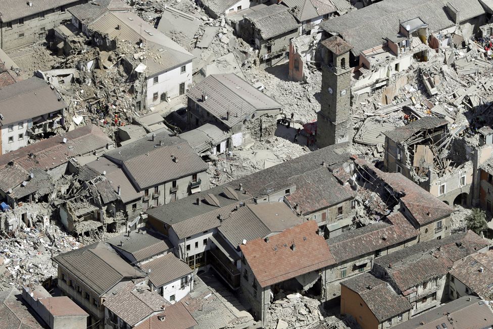
"Curajul nu se teme de cutremur" este o initiativa a radioamatorilor din Italia pentru a sprijini strangerea de fonduri pentru reconstructia uneia din zonele devastate de seismul din 24 august 2016, respectiv Arquata del Tronto.


Prin initiativa radioamatorului italian I6FDJ (Filippo), radioamatorii au sansa de a-si demonstra solidaritatea intr-un scop nobil, care va fi marcat printr-o placa evocativa care va fi instalata pe cetatea din Arquata del Tronto, simbol al regiunii si care va avea inscriptia "I RADIOAMATORI DI TUTTO IL MONDO HANNO PARTECIPATO CON IL LORO CONTRIBUTO ALLA RISTRUTTURAZIONE DELLA "ROCCA DI ARQUATA DEL TRONTO". 

Legatura inscrisa in log este in CW :-)


ISRAEL 70 Diploma

Well, I got this diploma for working several stations from 4X.
Why is so important to me? Because I made one contact on CW!


21 aprilie 2018

CW. "Inceputuri" re-loaded.

In pofida celor afirmate de unii radioamatori mai carcotasi, cum ca CW ar fi practicat de o cateorie de hami lipsiti de cunostintele de limba engleza, am decis ca trebuie sa ma apuc si eu de telerafie.
In ceea ce ma priveste, motivul este unul de ordin practic: imi doresc sa experimentez cu tot felul de echipamente cat mai compacte si portabile si telegrafia (CW) este unul din modurile de a comunica cel mai la indemana!

Pe langa statie si antena ai nevoie doar de un manipulator/cheie si de o pereche de casti. Evident, este nevoie si de ureche si antrenament pentru a receptiona...

O scurta digresiune: am terminat armata in 1990 la Transmisiuni... Acolo am facut Morse "ca Berila", cum se zice in jargonul militar... Am dat examen de clasa a IIa si asta zice in livretul meu.
Totusi, spre rusinea mea, de atunci si pana acum am abandonat problema. In mare masura si pentru ca dupa armata, desi am ascultat prin frecvente una alta, nu am reusit sa ma acomodez cu telegrafia radioamatorilor...
In armata foloseam radiograme cu seturi de 5 caractere pe care le "prindeam" complet detasati, aproape dormind, neinteresandu-ne continutul si codul Z- iar acestea au propria melodie- in timp ce in benzile de radioamatori melodia expresiei este cea care conteaza si trebuie sa si intelegi simultan cu receptia... E ciudata chestia, este ca si cum ai asculta pe cineva vorbind in aromana: prinzi cate un cuvant dar sensul iti scapa.

Sa revenim din scurta digresiune insa...

Primul pas a fost sa imi reamintesc "sunetul muzicii"...
Semnalele telegrafice nu se receptioneaza dupa numarul liniilor si al punctelor si nici nu e prea bine sa practici metoda "americana" cu "dit-dah" in care povestesti, de fapt, ce se intampla in difuzor!
Cel mai bine este sa incepi sa receptionezi semnalele telegrafice ascultand melodia fiecarui semn... Adica sa incepi de la o viteza de la care deja nu mai poti sa numeri cate puncte si cate linii! Asta inseamna cel putin 17-20 semne pe minut, viteza de transmitere a semnului! Importanta chestia asta cu "viteza de transmitere a semnului", o sa vedem mai incolo...
Unele semne au o melodie careia putem sa ii asociem o expresie, cum ar fi "mama-si-cu-tata" pentru "," , "alibaba" pentru "Y" ori "securitatea" pentru cifra "3". "Q" este "casca-pe-cap" iar pentru "L", expresia e oarecum indecenta in termeni civili dar in armata era o realitate incontestabila: "te-prind-te-rup"...


Cel mai la indemana a fost sa caut o aplicatie pentru telefonul mobil, una care sa stie insa sa transmita literele(semnele) la viteza mare insa cu spatiu intre ele, suficient cat sa ma lase sa asociez sunetului o imagine... imaginea literei.
Aplicatia la care m-am oprit dupa ce am testat cam tot ce este in Google play este "Learn Morse" si este scrisa de G0HYN.
Are posibilitatea de a receptiona interactiv (trebuie sa tastati corect semnul primit) dar poate sa transmita si texte si QSO-uri cu metoda Farnsworth, cea in care semnul are viteza reglabila separat de spatiul dintre semne. Cel putin la mine a dat rezultate optime, reamintindu-mi mai repede semnele la viteza mare dar cu spatii ample intre ele decat la viteza mica si "inghesuite".


Dupa o saptamana de receptionat cu ajutorul acestei aplicatii (evident, o pereche de casti va ajuta) am reusit sa descifrez tot alfabetul, inclusiv cifrele si semnele speciale (punctuatie).
Am practicat receptia cam 30 de minute zilnic, in seturi de 3 minute. Nu are rost sa devina plictisitor si nici nu este scopul metodei sa va faca sa adormiti...

Cat despre partea cu transmisul, asta este mai simpla decat receptia...
Intrucat nu am avut chef sa cheltui prea multi bani pe o cheie telegrafica iar Vibroplex-ul meu merge la viteza prea mare pentru mine, m-am gandit sa imi fac o cheie tip paddle.
Acum cativa ani (prin 2012, wow!), mi-am facut un touch keyer bazat pe un circuit specializat de la MicroChip AT42QT.
Din pacate insa, ceva nu ma prea multumeste la el si imi e greu sa spun ce... pur si simplu, nu ma simt confortabil cu el desi raspunde foarte precis.

Asa ca, am zis sa imi fac singur o cheie telegrafica tip single-paddle, bazata pe lagarul de la un hard-disk si alte cateva maruntisuri de prin "cutia cu maimute".

La manipulator am conectat keyer-ul  facut cu un PIC16F628A dupa schema lui DL4YHF (versiunea lui IZ4KBS) - unul din primele mele proiecte cu microcontroller- acum foarte multa vreme si tot atunci a fost incarcat acumulatorul...  Are doua memorii care insa nu pot memora mesaje lungi dar sunt suficiente pentru  apelul general si incheierea de QSO. Keyer-ul permite modificarea vitezei folosind direct cheia CW tip paddle, spre deosebire de versiunea originala, care folosea un potentiometru.

Pentru a-mi fi mai usor sa ma verific la transmitere, am preluat un proiect mai vechi de-al meu, un decodor CW cu autocalibrare a vitezei (bazat pe Arduino) si l-am conectat in paralel cu transceiver-ul, la iesirea keyer-ului.  Asa pot sa verific imediat daca am transmis ce trebuie sau a iesit o prostie... Desigur, e mai mult un moft pentru ca urechea e cel mai bun instrument pentru asa ceva :-)

Bun, deci aveam cam tot ce imi trebuie, mai putin indemanarea slefuita. Am zis totusi sa incerc marea cu degetul si am activat functia BK-IN pe transceiver, adica ce bateam eu in cheie incepea sa fie auzit si in eter... Pentru inceput, am zis sa dau cu circa 30W ca sa pot primi raspunsuri de la statii cu semnale puternice, sa imi fie mai usor la descifrat...

In banda de 40m, 20 aprilie 2018 am dat cateva CQ DX DE YO3HJV. Am auzit o rafala ca raspuns... Brusc, tot ce stiam s-a dus naibii si nu am reusit sa decodez nimic! Era pe la vreo 30 WPM...
Asa ca am batut "???" la vreo 20 WPM si cu spatii generoase intre semne, cu speranta ca statia corespondenta va micsora un pic viteza...  Uitasem pana si de "QRS" (micsorati viteza de transmitere)...

Pe la vreo 24 WPM transmise de celalalt, am reusit sa prind indicativul, UT7LW. Folosind o ciorna pe care mi-o facusem cu cateva expresii, am reusit sa transmit controlul si numele operatorului. Greseli cat cuprinde (HI) dar si faptul ca e prima mea legatura "la cheie" in CW... Din fericire, Geo (UT7LW) a fost intelegator si a avut rabdare sa terminam acest QSO; i-am trimis si un e-mail in care i-am multumit :-)

Apoi a fost ON6KZ Peter dupa care IU5ASA cu care chiar am stat nitel "la taclale" la circa 16 WPM, el lucrand la manipulator clasic (ciocan) si avand o "melodie" frumoasa... 

Cam asta a fost prima zi de CW in eter...


LATER EDIT:

In noapte, tarziu, am facut un test. Am setat puterea statiei pe 0W si am pus pe automat keyer-ul integrat in statie sa transmita "CQ CQ DE YO3HJV DE YO3 HJV BCN MODE K".
Spre surpriza mea, am fost raportat de Reverse Beacon Network in cateva tari din Europa cu semnal foarte bun! Pe 0W statia mea are circa 600 mW iar antena este o antena verticala plasata direct pe sol...


CU AGN DE YO3HJV


Most viewed posts in last 30 days