From time to time I use to set the dial of my HF radio to some frequencies where voice QSO’s are expected - like local nets or WWF/SOTA/POTA.
The noise is annoying for me and my family. One solution is to keep the volume very low but this means I miss the calls when I am not near the radio.
Another one is to use the “classic” Squelch circuit that almost any radio with FM mode had it but this works awkward in HF, passing any signal above a certain energy level, including QRM/QRN.
I have had a Codan radio and I remember a nice (and rare) feature it had, a Voice Squelch which let pass the voice and muted other QRM/QRN.
Wouldn’t be nice to have the same function on my IC-7100???
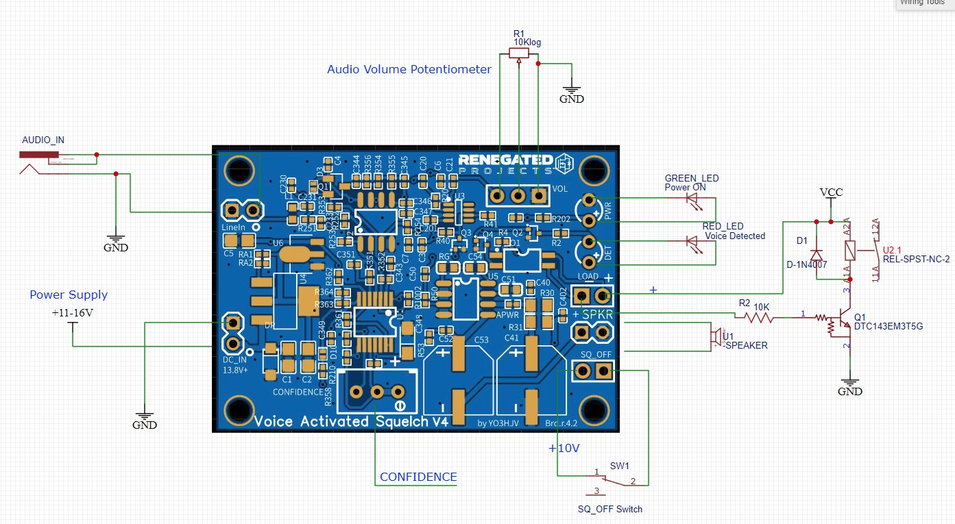
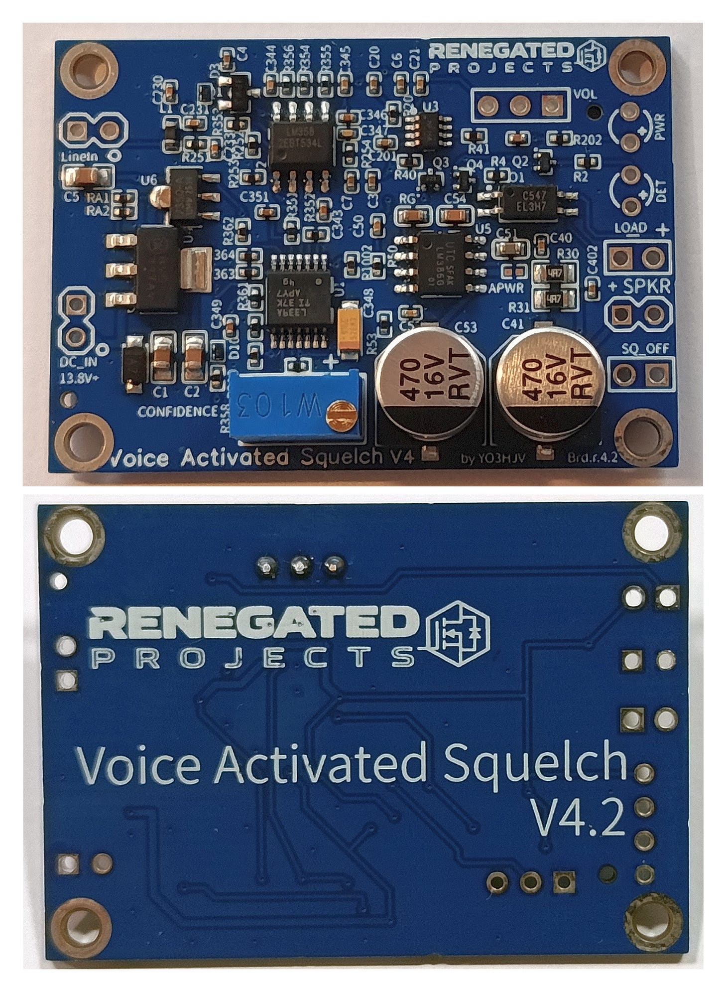
This is why I made VAS-V4, described here.
Adrian


