Showing posts with label DIY. Show all posts

18 October 2024

LoRa APRS with Meshtastic DevBoard

After I played a little with my Meshtastic Development Board I previously made (and write about) I decided it will be nice to give it a try into LoRa APRS.

This raise some issues about how different modules are connected to the GPIO's of the ESP32 in my configuration.

I was directed by some early adopters in Romania to the CA2RXU web flasher where I found that the Tracker FW can be loaded into a pretty good selection of boards.


But, what board from those would be compatible with my one? Hmmm.... this would require some research!

First, I had to go to CA2RXU's excellent repository and find some clues about pin mapping; how the LoRa transceiver is connected to the ESP32 on various boards in order to choose the proper version of the already compiled FW from the web flasher tool...

Yes, I could compiled it myself but, apart from being a brave ham, I like to cut corners because I'm a lazy one!

Using the already compiled FW will be a good "investment" because I can keep up with the future versions without going to the compiling process everytime a newer version is released.

Flashing the LoRa APRS I-Gate was easy and I already had one working on my bench but the tracker is a different animal because it needs the GPS input to really be usefull as a "tracker"!

So, I land onto the GitHub page of the project and searched for anything that could hint to my problem. Soon I found boards_pinout.h where various ready-made boards are described.

LoRa module is tied to the ESP32 using this diagram:

MISO > D19

MOSI > D27

NSS/CS > D18

SCK > D5

RST > D23

DIO0 > D26

so I searched for this particular definition.

I found two of them that could suit my needs.

First was the TTGO T-Beam family that catched my eye. Almost all of them have the LoRa transcever connected as I needed.

The main problem with the newer versions of the BOARD (!!!) have the battery management circuit APX192 and this is used for informations about the battery voltage.


Well, my board is reading the voltage with ESP32's ADC so, using the firmware could cause some problems. Or not. I don't want (yet) to explore the full code to see how APX192 is integrated into the workflow therefore I choose an early version, of T-Beam FW, the 0.7.

 
I connected the GPS Tx to GPIO 12 as defined into the code but, to my surprise, a message on the small LCD told me that there is no GPS data incoming.
Scratched my head a few hours... Everything was right on the HW side but no GPS valid frames and a suggestion to reset it. Well, that was not an option because I was sure my GPS junk was OK because I previously tested on Meshtastic and it performed like expected!

Left the things like that at around 2AM and next morning I was eager to see the schematic of the TTGO TBeam 0.7... Where the heck that GPS Tx was tied to ESP32?
The schematic is hard to find but a picture of the board told the whole story!
The GPS Tx was connected to GPIO 34!!!

Well well, you little TBeam prick, gotcha! I connected the GPS Tx to GPIO 34 and, voila! that message dissapeared and soon a fix was achieved!

Looking into the code I saw that another board had the same pinout definitions on LoRa TRX with some minor variations.

OK, so, what else do I need to look for? 
The Battery ADC..
 
Most of them are at GPIO 35 which is the same as my dev board so, "cheked".
 
Button? 
Well, I might be a nice feature but I think I can use the tracker without it after I tested the programming interface (web based) -most of them are on GPIO's that are not available on my board...

So? I think we are good with GPS and LoRa Trx working properly!

The next step was to play a little bit with the firmware for other boards and found one that fits well:
TTGO_T_LORA32 V2.1


The blue LED connected to GPIO 15 is there to show me when the tracker is transmitting because I intend to use it without the OLED display; that was just to see how the things works..
 
The battery voltage is not correct, it should indicate 4.2V but this is due to the voltage divider that have different resistors than the TBeam original board for which the FW was written. Yeah, Yeah, I know, I can change the ratio by replacing one resistor... I will think about it, I promise!


73!


30 September 2024

Meshtastic ESP_32 DevBoard

Everyone know MESHTASTIC!

It is the promise of a new communication meaning over long distances and without any infrastructure needed.


Somethink preppers love!

This communication system has two important features that make it particularly effective for facilitating message communication over long distances:
-LoRa type modulation;
-Self-configuration of devices in a MESH network.
 

I will not go into details, Google is your friend and you will learn everything about LoRa modulation and MESH networks.


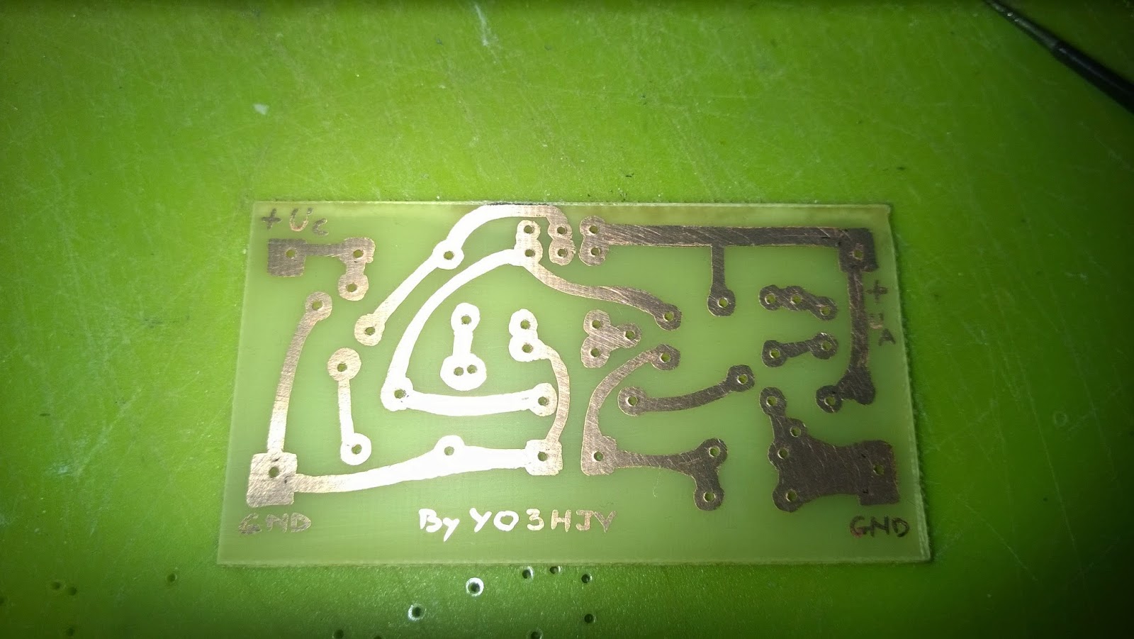
In this post I want to talk about how I made my own devices, using cheap modules available on various sites in China.

Things are not so simple; you need some knowledge in electronics to deal with the ready made modules on the market or you can order some 100% finished products. Then you need to program them but that's pretty straightforward as it can be done via a web flashing tool that work with Chrome browser.

But if you are a BRAVE HAM like I am and you already have some modules in the junk box, you may want to make it more flexibile from more basic components.

First, the ESP-32 to SX-1278 module (LoRa Transceiver) is this:


Pretty straightforward; the LoRa TRX communicate with ESP32 via SPI interface.

As we're gonna use the already compiled firmware "Meshtastic DIY", I used the connection from that firmware:

MISO > D19

MOSI > D27

NSS/CS > D18

SCK > D5

RST > D23

DIO0 > D26

But, if I was going to design the board, I must do there something to have some features for future experiments...

So, a number of GPIOs were provided.

A special circuit to activate or deactivate the GPS to save some power was added; the special High-Side switch circuit AP2151 was put into design.

Because, sometime, the circuit is not available, U3 can be tied to 3V3 to keep GPS permanently powered.


Then, two 18650 LiIon battery holders were provided, and a TP4056 module to charge them.


Some users complained about unstable operation when the voltage of the battery drop beyond 3V so, a watchdog circuit was added. This monitor the voltage of the battery and, if the voltage drop under 3V (or any other voltage of the user's choice), the ESP32 will be kept into RESET mode until the battery is recharged.

The circuit of choice was TLV840MADL30DBVRQ1.


What other features the board have?

Well, maybe I want to have an external antenna; the SX1278 module came with some kind of short antenna at the end of a thin coaxial pigtail but an external one increase the range of the radio link.  I sometime want to use SMA antennas but to be able to use BNC ones if I want to!

Being a BRAVE but sometimes UNDECIDED ham, I provided the PCB for both kind of connectors. Just a small cut-and-solder of that coaxial and the problem is solved!


The GPS of choice ISN'T a uBlox but the but, when designing the PCB, the footprint of the Neo6M was satisfactory to allow installation of several types.


What other feature? Well, a voltage divider to measure the battery voltage, I2C connectors provided for an OLED and for a BME80 pressure/temperature monitor and, of course, a lot of GPIOs spreaded all around the board but some grouped together for some sort of a future expansion board on pogo pins...

In the development process, I ordered the PCB's with some componentes mounted directly in China.

I hoped to solve three problems simultaneously: make the PCBs, buy the components and, if they have to come together, they'd better come mounted on the board! But the count at the fair doesn't match the count at home so, when I received the first version of the PCB, I realized that I had made some major mistakes, which could only be corrected by redesigning it. So, I redesigned it, changed its color from black to blue, made it thinner, from 2mm to just 1mm and ordered it without the components mounted because I was going to transfer them from the V1 boards to the V2 boards...


Then, after I had done the transfer on all ten boards, I realized that in the selection process I had ordered the wrong circuit... AP2141 instead of AP2151. The difference? Well, the former commands the GPS when the command pin is grounded and the later, correctly, commands the GPS when it receives the positive voltage command. So I've hit the wall again...

Fortunately (remember?) I provided a hardware mean to permanently power the GPS... :-)


Next comes replacing that circuit, then will be another hassle...

That's when ham radio bravery goes out after midnight, that's when I get these ideas! 

You can find all the relevant documentation on my Github repository.

LE:

Farnell was very fast and the correct AP2151 is now installed on all boards and everything is performing as expected!

Cheers!


09 April 2017

Dipol VHF (UHF) simplu

M-a intrebat un amic ce antena de VHF sa isi faca. Imediat m-am gandit la un dipol deschis, ca varianta optima eficienta/pret.
Ca materiale, am folosit o teava din aluminiu, de 20mm grosime in lungime de 1m si o bara de PVC, tot de 1m lungime precum si o mica platbanda de circa 25mm latime si 1mm grosime in lungime de circa 45mm.

Pentru inceput, am facut suportul (consola) din PVC. Am taiat din bara de PVC o lungime de 30cm si am marcat-o la jumatate. Pe aceasta bucata se vor prinde elementele dipolului.


Restul de circa 70 cm urmeaza sa fie "consola"; la unul din capete am prelucrat-o cu un Dremel astfel incat sa fie concava si sa se imbine pe generatoarea bucatii de 30 cm. 
Am pregatit o mica cantitate de rasina epoxidica cu intarire rapida, am imbinat cele doua bucati si le-am prins cu un holtzsurub.


Apoi, am taiat in doua bucati de cate 50 cm teava de aluminiu si am realizat gaurile de prindere cu o bormasina cu coloana pentru a asigura perpendicularitatea pe generatoarea tevii.


Cele doua bucati de teava de aluminiu se introduc pe bratele suportului in forma de "T" din PVC apoi gaurim si PVC-ul pe tiparul gaurilor din tevile de aluminiu.

Din bucata de platbanda am facut suportul mufei BNC mama cu flansa patrata. Aceasta se prinde cu un surub M4 pe una din tevi, pe gaura realizata la 7mm de capatul tevii. Firul central al mufei se conecteaza la cealalta teava, tot la prima gaura.

Antena se realizeaza in circa o ora cu un cost total, circa 30 lei...

Bratul consolei (circa 70 cm)  asigura instalarea la distanta de cel putin 50 cm (L/4) de un pilon. Atentie insa, pe directia pilonului, diagrama va fi cardioida cu o atenuare de circa 3 db!

Masuratoarea de SWR arata 1:1.2 in banda 118-138 si circa 1:1.5-1:1.6 in 140-146 MHz cu 1:1.6 in 435 MHz, apropiat de simularea in MMANA:


Pentru un acord perfect in 145 MHz, lungimea celor doua elemente ale antenei trebuie redusa la circa 49 - 49.3 cm. Eu le-am pastrat de 50 cm pentru banda aero.

Cum arata antena:

Este pusa cu GND in jos :-) dar merge la fel si invers :-)))


25 September 2014

LiIon charger with LM317 and Cutoff circuit - Part I

Very often I need to charge one or two series LiIon cell for my experiments.
I do have a sophisticated battery charger and analyzer but I don't want to use it every time.
I need something simple yet safe.
There fore I came to a nice shematics here.


It is a very simple schematics using just one LM317 and two NPN transistors.
I made some modifications.
The most important is R7 which is 6 Ohm for a 210 mA current.

Despite the urban myths, the Li based batteries are very safe at charging if you respect two rules:
1. No more than 4.2 V per cell
2. No more than 1.5 C (thats 1.5 x Nominal capacity in A) charging current.

The main advantage is that at the end of charging, when the battery has the desired voltage - in our case, 4.2 V/Cell, the charging current drops to zero. The bonus is that the LED lights during the charging phase.

Yes, I know, there is CAD but I like the old fashion way to make a PCB. By hand with a fine marker...

Here are some pictures....


I plan to put this with a 12V/2A SMPS into a small box.

23 April 2014

1:1 UnUn, Choke BalUn

A few days ago I noticed that, while trying to work on 40m from mobile, my Icom IC-7000 suddenly stops, powering off.
So, investigating the trouble I put a (very) Ugly Balun at the output of the radio.
The problems went off so I planed to make some sort of Choke balun.
This broadband transformer is a 1:1 and block the current mode current.
Here it is the making off:


LE:
The main reason for making it with two RF connectors is that the choke is used in mobile installation and after it there is a small lenght of coaxial cable.
 73 de YO3HJV

Most viewed posts in last 30 days