A request from a fellow ham made me revisit an old project, and Arduino based repeater controller.
This lead to an iterative process to upgrade it from a simple Carrier Detect repeater to a more versatile one, that can use RSSI signal to activate the repeater. That's because the OM didn't have a Carrier Detect output on the radio that was available for his repeater.
In this version, the Mode can be selected by connecting a pin to the Ground) before the repeater is powered on.
Anti-kerchung was implemented for both Carrier detect and RSSI modes and in the later one, a hysteresis was defined.
Playing with Arduino and it's C++ I often use timed tasks.
Basically, in Arduino you can do things at specific interval either by adding delay() at some strategic points or using wellknown non-blocking code:
const unsigned long interval = 1000; // Interval for LED blink (in milliseconds) unsigned long previousMillis = 0; // Variable to store time since last LED update
int ledPin = 13; // Pin for the LED
void setup() { pinMode(ledPin, OUTPUT); // Initialize LED pin as an output }
void loop() {
unsigned long currentMillis = millis(); // Get the current time
// Check if it's time to update the LED if (currentMillis - previousMillis >= interval) { previousMillis = currentMillis; // Save the last time LED was updated digitalWrite(ledPin, !digitalRead(ledPin)); // Toggle the LED state }
// Other non-blocking tasks can be added here }
What if, the code need more than one timer?
Well, we can use multiple timers like that!
While this is the simple and easy way, in a big code we start loosing track of what does what and if the code is big, each byte counts! Let's not forget that each unsigned long type variable cost us 4 bytes of precious memory; each byte consists of 8 bits, and an unsigned long on Arduino is a 32-bit data type, so it occupies 4 bytes (32 bits / 8 bits per byte = 4 bytes).
I have a program in which I have to test multiple timers with multiple distinct intervals and the memory cost was huge.
So, I stayed and think and found a very elegant solution.
While I may reinvented the wheel, I think it is nice to share it with you!
It is all about making a single time measuring function and asign boolean variables to keep track of various things.
unsignedlong previousMillis_ONESECOND = 0; // Variable to store the last time the ONESECOND was flipped
constunsignedlong interval_ONESECOND = 1000; // Interval at which to flip the ONESECOND (in milliseconds)
bool ONESECOND = false;
void loop(){
updateONESECOND(); }
void updateONESECOND(){
unsignedlong currentMillis = millis(); // Get the current time
then, I have other functions that check various conditions AND bool.
For example, a function that blink a special character on a LCD:
bool ProcessSTART = false;
voidfLCD(){ // alternate symbol at a rate of one second while StartLog is activated
if(ONESECOND && ProcessSTART){
printFN_Char();
}
else{
printFP_Char();
}
}
the other bool ProcessSART is flipped in other part of the program.
In other functions you can count the number of seconds using this tic-tac function and get other intervals derived from it, using less bytes in a simple arithmetic function.
It's like using an external time generator for all the functions in the code.
I have a lot of those little boards made around a TP4056 IC.
According to the datasheet:
The TP4056 is a complete constant-current/constant-voltage linear charger for single cell lithium-ion batteries. Its SOP package and low external component count make the TP4056 ideally suited for portable applications. Furthermore, the TP4056 can work within USB and wall adapter. No blocking diode is required due to the internal PMOSFET architecture and have prevent to negative Charge Current Circuit. Thermal feedback regulates the charge current to limit the die temperature during high power operation or high ambient temperature. The charge voltage is fixed at 4.2V, and the charge current can be programmed externally with a single resistor. The TP4056 automatically terminates the charge cycle when the charge current drops to 1/10th the programmed value after the final float voltage is reached. TP4056 Other features include current monitor, under voltage lockout, automatic recharge and two status pin to indicate charge termination and the presence of an input voltage.
This might be a problem with low capacity cells because to keep the charging in the safe area, the charging current must not exceed 1C (C=designed capacity).
Charging above this might give a temperature rise and this is not good for Li based cells. Of course, there are specific cells that accept charging currents above this safety limit but those are special ones thus not taking risks is a good approach.
We can conclude that we can use this circuit directly connected to a small Solar panel able to output 6V.
But what about the current?
Well, the charging current is set by the value of a resistor, Rprog in the test circuit below:
The value of this resistor determine the charging current as per the table below:
On some modules, the resistor is marked "R3" but anyway, you can easily found it by tracing the circuit from the pin#2 of the IC; in the photo is the one below the little capacitor on the left side of the circuit:
From the factory it came with a 1K resistor which, according to the datasheet, correspond to a 1000mA (1A) charging current.
I changed it with a 2.2 KOhm one and the charging current dropped, as expected, around 500mA.
For final, here is what this module wants to tell us, based on the LED status:
I have an old Proxxon tool and, like many old power tools, the built-in speed controller is not working anymore.
So, I was thinking to do a separate box to set the speed because the actual method is not so suitable (altering the output voltage from my SMPS). You know, there are other "things" connected to it and modifing the voltage can harm them...
A DC current regulator was out of question because the Proxxon (like Dremel) need big currents when is loaded and the next thought was to make a variable PWM controller. So I searched into my boxes for a NE555 circuit and found a NE556 which is, basically, two 555 in the same IC.
I started to sketch the schematic and put it on a breadboard but there was too much soldering... HI HI :-)
Searching for a suitable case, I found one from an old project, already cut to accomodate a 2x16 LCD so I start to contemplate the possibility to make a speed controller which will show me the percentage and the input voltage and, why not, enable me to control other DC power tools.
I also found a small PCB already made for Arduino Pro-Mini and parallel controlled LCD so, i already had a good start!
Using PWM to controll DC motors is pretty convenient because the DC motor will "convert" variable width DC pulses into speed due to mechanical inertia. The most important thing is to find a semiconductor to work as much as possible to a switch!
Regular bipolar transistors are not suitable because they have a relative big resistance when the "switch" is closed so I decided to use a MOS-FET transistor.
I searched for one with a small Drain-Source resistance and found in my spare parts a IRF3205 which is advertised as a low resistance MOS-FET:
Of course, there are other suitable transistors but I wanted to have one that can handle some current without radiator...
Some words about the schematic
click on the picture for greater resolution
The working principle is simple; the speed potentiometer value is read by ADC (by reading the voltage of the wiper) and the value is converted from 1024 values into 255.
Then, this value is used to draw a nice bargraph, to print the % value and to generate the corresponding PWM value on pin 10 which will drive the MOS-FET transistor.
After testing it, I thought it was nice to have the input voltage on display so a voltage divider was made to be able to measure up to 30V with some accuracy.
My Arduino Pro-Mini was the 5V version so I choose a 7805 LDO to get those 5V for the board and the LCD. The board was powered by the RAW input, after the on-board voltage regulator.
Some words about the voltage divider and voltage measurement calibration
Arduino ADC's can measure 0-5V. Actually, the maximum value that can be measured with the ADC is precisely that of the Vcc applied to Arduino! So, in our case where the 5V are externally regulated from a 7805, we must measure the voltage at the RAW pin where 5V is applied. Usually the voltage is in the 4.9-5.1 V range and 5V is pretty accurate but if you want to have a greater precision, just replace "5" with the measured voltage in the code.
The voltage divider was made with what I had in my spare box, you can replace R4 and R5 with your values but keep in mind you must have a ratio able to keep the voltage at ADC port under 5V for the maximum voltage you want to use the device!
In the code, there is a "divider ratio" variable. This is how I get it:
Using this online voltage divider calculator, I used the following values, you can replace them with yours:
Input voltage: 12V
R1: 68 KOhm
R2: 5.1 KOhm
I got 0.837 V after the voltage divider.
The voltage ratio is therefore: 12/0.837 = 14.336917.
Of course, this is the theoretical result!
In practice, the ADC have it's own impedance, a stray resistor in DC so the real value of the voltage ratio is not so precise. Also, some errors will be present due to the real values of those resistors!
Some tweaking is needed to have a proper voltage indication so I set the voltage input into the device at 13V and on the LCD I got about "13.9V". I start to make some fine adjustments on that value (I did not calibrated the ADC reference too) and I ended with the
float divider_ratio = 13.1386;
which gave me pretty precise readings from 10 - 24V.
I think you got the ideea on what to do to your voltage divider to get it work right!
This was made and tested on my Xiegu G90 and it is working very smooth and nice. However, your mileage can vary from similar experience to magic smoke release! Bla bla bla, you know the text...
This PTT sequencer is designed for Voice operation and will not work on CW!
While other solutions can be take into account, using a small Arduino Nano to take care for timings on a PTT Sequencer is the most elegant solution.
If it were for me, the device would stand in my mind only but I made a promise to help a fellow ham and this is how this was born.
First step was to find a small and cheap RJ45 Ethernet adapter like the one in the picture;
This is very easy to open and inside there are wires from side to side.
Carefully identify the wires for GND, PTT and + 8V
Cut them then, on the GND and +8V solder another piece of wire. These two will be still linked but you must take out the GND and +8V to power the Arduino.
The PTT will be electrically split. one wire will go from the radio to the sequencer and the other one will go from the Microphone PTT to the sequencer.
I forget to take pictures in the process, this is how it looks finished. You can see a split wire soldered then to a third one, I think this is the GND one.
And here is the schematic, for the brave ones! You can click on it to make it bigger.
A few words about the schematic:
I choose to provide two delayed outputs ACC_A and ACC_B because I thought someone will use not only a QRO after the radio but also an antenna switch or, why not, some sort of "OnAir" light!
The outputs are isolated with the help of two optocouplers which keeps the current draw at a minimum.
There are two important things to consider when using optocouplers. The first is that they are polarised so you must pay attention when you connect accessories. The second one is to keep an eye to the maximum current draw by the accessories. With PC817, the maximum current is around 50mA@6V; if this is not enough, a relay has to be used.
I also used optocouplers on the PTT switch and on the PTT output to the radio but, because those I/O are not isolated, common transistors can be used.
Last but not least, the circuit draw it's power from the +8V line which came from the radio. In the radio 8V is produced with a 7809 therefore the approximative 70mA drawn by the sequencer will not be a big issue.
Just after i finished drawing the schematic for the device I added, for further implementation, some circuit parts for a Courtesy Beep which can be launched at the beginning or/and the end of transmission just by a few lines of code.
How is the device working?
Well, the magic is in the code; because some accessories are electronically switched (with PIN diodes) and other are "classy" (old fashion relays) I thought some sort of variable delay can be usefull.Therefore, with the help of two SPSD DIP Switches we can choose from 4 values. Because 4 is too much, we will have 3 timings and one "test" position with a very long delay, to test the proper setup.
Because the sequencer is code-defined, I will refer to my version of the code:
With the radio in OFF position, a small Ethernet cable will connect the sequencer to the radio and the original curled cable from the sequencer to the microphone.
With the device not connected, you can choose the timing according to the table above.
Power on the radio; the RED LED will briefly flash and right after, the GREEN LED will stay lit. This is to know the boot procedure was finished and everything is OK.
NOTE: the timings can be changed BEFORE powering the unit.
Any change in the switches must be followed by a RESET (or POWER DOWN/POWER UP).
So, let's assume we choosed 50mSec delay:
At POWER ON on the radio, all ACC are OFF and radio is in RX.
When the PTT is pressed, ACC_A switch ON, wait 50mSec, ACC_B switch ON, wait50mSec, radio goes TX, operator start to speak.
When the PTT is released, radio immediately go RX, wait 25mSec, ACC_B switch OFF, wait 25mSec, ACC_A switch OFF.
So, if we have Antenna switch on ACC_A and QRO on ACC_B, the antenna switch goes ON first and OFF last, radio switch TX last and RX first and ACC_B is between.
On the other hand, if you use just QRO with the radio, with 50mSec timing set, if you use ACC_B you will have a 50mSec delay in consideration to the radio Tx but if you connect it to the ACC_A you will have the double, 100mSec.
You will notice a difference in PTT press and PTT release timings, this is because when PTT is released, the radio goes immediatly in Rx and there will be no RF present on the switching circuits therefore we can cut some delays there. The Tx to Rx delay was implemented as interval/2 in this case to speed things, especially for pileups or contests when is important to be fast on receiving.
The RED LED will light when the radio is keyed into TX and it is also "code driven" so can be associated to other functions.
Sometimes in the lab there is need to monitor the power parameters during some period of time and put it on a nice graph.
Because I couldn't find something like this and because it is fun to make things, I start to wonder what if I put an Arduino on a power supply!
So, the lab supply must have:
-Variable voltage between 1- 14.4V
-Current monitor
-Start/Stop
-Overcurrent protection
-Serial output with time markers
Because I am lazy, I used some ready-made modules.
The main power supply is a modified 12V/5A SMPS; with a little tweak it now deliver 17V/4A.
The modification was made in the feedback circuit where the TL494 reference is compared with the output voltage.
The variable output voltage is made with a DC/DC Step down module able to handle constant voltage from 1.25 to Vsmps - 2V at around 5 A.
The output voltage and current are measured with the Arduino ADCs and I used two 2.5 LM4050 precision shunt reference in series to have Aref at 5V.
The DC/DC Step down is controlled with a PCF optocoupler driven by a digital potentiometer MCP41010 on SPI.
The output relay is used for fast protection as a "crowbar" circuit and, in the future, will connect the output to a controlled discharge circuit to characterise batteries.
By code, this power supply can be used to deliver regulated voltage and monitor the current or to charge various batteries.
A few years ago I came around a nice POS Vacuum Fluorescent Display.
The model I have is CD7220 and it is designed to show information about a customer purchasing in a nice blue-green colour onto a Vacuum Fluorescent Display with 2 rows and 20 columns.
I put it on my bench and gave it a long look seeing on it's two rows a lot of possible things. From clock to some informations extracted from CI-V from my ICOM radios, various configurations scrolled in my imagination.
I started to search for some documentation and found the datasheet then started to look inside to see how it was interfaced with the POS cashier machine.
The VFD is interfaced via RJ45 connector and from the signal perspective, a HIN232 circuit handle the conversion between RS232 serial COM port to TTL UART. Basically, this circuit is a clone of Maxim's MAX232 RS232<>TTL level convertor.
The backup battery, a rechargable Li cell was dead and I replaced with a 5 V/4F capacitor. This is enough to keep the time for some time when power is off.
Because the circuits in the VFD need 24V, I put inside a DC/DC boost convertor so I can power the board with anything above 5V and below 24V. Yeah, I know, this is too big for this project but this was laying on my junk boxes here... You can use any boost DC/TS that can sustain 5W in a close box for extended periods of time.
After setting the Time and Date as above, use the code provided on the Github, insert the correct UTC offset for your region and then upload the code to Arduino.
The code is commented and it is self explanatory; before you upload it, check the correct offset for UTC.
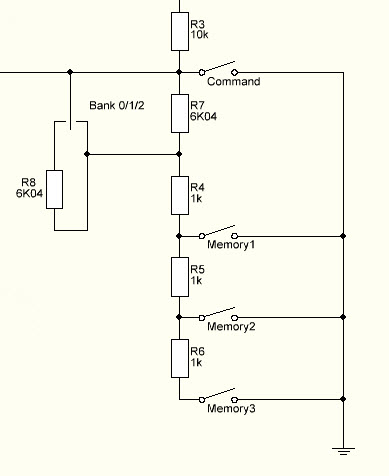
I decided that I have to make another K3NG keyer, this time full featured in order to test some things. Therefore, I started to make it "real" not just a breadboard full of "dead bugs". Looking into the code, I found a very interesting feature that provide 9 memories with only 3 buttons. The solution is proposed by Dietmar, DL2SBA and consist in both hardware and software modifications of the original source code (which is already big and full of stuff).
Choosing to have Command Buttons AND DL2SBA bankswitch resulted into error.
I gave it a shot and when Command Buttons feature and DL2SBA bankswitch feature are selected, the compiling ends into "exit status 1 invalid preprocessing directive #elseif" somewhere around the line #8632...
Therefore, I commented the bankswitch and get to my workaround! And this is my solution, below.
It's just a "shift" of the voltages read by the ADC; each position of the switch is "moving" the voltage with 3 memory places. Therefore, we have the same 3 banks but with no software hassle. Just check to see if in the "keyer_settings.h" there are at least 10 buttons (1 COMMAND and 9 memory).
Basically, my solution is similar to what Dieter proposed but it uses the original code without rewrite the variables on the ADC array. And gave no compile errors, of course. 73!
Just for fun and to use the Pandemia holiday I thought will be interesting to have a little remote for the Voice and CW memory.
While the Voice memory callback is relatively simple with CI-V protocol, for CW memory there are no commands provided by ICOM.
Therefore, the keyer will store the preset messages (10 messages) and send them using a 4 x 4 keypad.
The uC of choice is an Arduino with Atmega 328 on UNO platform.
The keypad is also used to Power On and OFF the radio and TUNE the ATU (I use an AH-4).
The 4 x 4 keypad is able to send:
-In CW, 10 preprogrammed CW messages, each of 128 bytes;
-in SSB, AM, FM, 8 prerecorded voice messages
-"A" is Power ON
-"B" is Power OFF
-"C" is TUNE Here is a small video on youtube about this Here is the code
For some time I wanted to put LED DRL (Day Running Lights) on my car.
It was some pain in the a*** to run the wires into the car and I was looking for a simple and elegant solution.
And I was hit by inspiration!
I found the solution!
A DRL which power ON at the engine start and goes OFF a few minutes after the engine is stopped!
But how?
Simple, with an Arduino we test the battery voltage and decide to go ON or OFF because the lead-acid car battery goes under 12.8 V when the engine is stopped and above 13.4 when the engine is running!
1. Install Sonoff-Tasmota firmware following the instructions here. 2. Default relay output on NodeMCU is GPIO 12 on ESP8266 (D6) on LoLin NodeMCU clone).
3. In the photo attached is NodeMCU LoLin clone pinout description.
4. Prepare RaspberryPi for DOMOTICZ.
Tried to reflash it with NodeMCU formware programmer under Windows 7 environment but no success... The flashing stops somwhere around 4000 B upload and sent a failure message then stops.
The programmer was a FTDI USB to TTL programmerset on 3V logic.
After two days of wondering what is wrong and trying various combinations of hardware, I found a lot of comments somewhere about the same problem.
The solution is simple and involve a tweak on the COM port settings.
1. Go to DEVICE MANAGER and find the USB Serial Port under the PORTS.
2. Click right and select PROPERTIES.
3. Go to PORT SETTINGS tab then ADVANCED.
4. Set RECEIVE (BYTES) from 4096 to 512.
5. Click OK whenever is asked to get out from that settings.
6. Connect FTDI USB to TTL adapter set on 3V to the Adafruit Huzzah ESP8266 breakout board
7. Start NodeMCU formware programmer, go to ADVANCED, check for baudrate to be 115200, 4MByte, 80 MHz, DIo.
8. Go to CONFIG and load the proper bin.
9. On the ESP board, push GPI0 button, keep it pushed then push RESET. Release RESET then GPI0. The ESP8266 get into flashing mode.
9 Go to OPERATION and click FLASH. The window should populate with the MAC addresses of the ESP-12 board and the programm should start and the progress bar should advance. Slow but steady!


