Very sad news just received from the daughter of John, ON4UN
It is with sadness, but also gratitude and pride, I have to let you know my father John ON4UN, has become silent key.
John’s health has steadily deteriorated throughout the year, but in the last few weeks he was home with us where he peacefully passed away yesterday November 9.
Ham Radio, and especially Low Band DXing, were my father’s lifelong passion and always had a strong presence in our house. Sometimes literally, when many of you paid us a visit or a group of DX’ers came over for a weekend of contesting. At other times in the background, when my dad was working on a project or experimenting with new equipment or antennas.
Though I don’t have a call-sign, I very much feel part of the big radio family and always will. I am very proud of everything my father has accomplished together with you, and I am grateful to the many of you who have given him so much joy over the years. We will miss him dearly, but we take comfort looking back on the beautiful life he lived as a member of the wonderful Ham Radio community.
We are planning a digital farewell ceremony on Saturday November 21st and will keep you updated on practicalities.
If you would like to send us a message please mail to ON4UN.SK@gmail.com – John’s old e-mail account is not in use anymore.
In the meantime, you can pay him a visit at QRZ.com where he always kept his resume up to date.
Odata cu inceperea noului ciclu solar,
conditiile de propagare in benzile de unde scurte (HF) sunt asteptate sa se
imbunatateasca treptat pe parcursul anului 2021; aceasta noua initiativa este
destinata sa ofere vanatorilor de DX-uri motivatia de a realiza legaturi si,
drept urmare, sa sustina, sa imbunatateasca si sa promoveze activitatea
radioamatorilor prin utilizarea modurilor de comunicatie “traditionale” ca telegrafia
(CW) si fonia (SSB). Prin aceasta initiativa inedita, pe care o numim “Ultra-maraton”,
ne dorim sa motivam operatorii sa realizeze pe parcursul intregului an legaturi
cu indicative unice DX.
Perioada
de desfasurare
1 ianuarie 2021, 00:00 UTC – 31 decembrie 2021, 23:59 UTC
Moduri
de lucru
CW si SSB. Intrebare: De ce nu si MIXT?
Raspuns: din motive de simplitate. Pot fi utilizate diverse programe pentru
log. Tinerea scorului si livrarea log-urilor se poate realiza cu o plaja
variata de programe de concurs; nu toate suporta modul “mixt”. Mai multe
detalii despre programele ce pot fi utilizate vor fi furnizate pe site,
ulterior.
Categorii
Participantii pot alege una dintre cele 3
categorii in functie de puterea utilizata, indiferent de ce sistem de antene
folosesc:
HIGH POWER – Puterea maxima permisa,
potrivit autorizatiei
LOW POWER – 100W maxim
QRP – 5W maxim
Benzi
10, 15, 20, 40, 80 si 160 metri.
Intrebare: De ce nu si benzile WARC?
Raspuns: Din acelasi motiv pentru care nu exista si participare la “mixt”. Mai
multe detalii despre programele ce pot fi utilizate vor fi furnizate pe site,
ulterior.
Scopul
concursului
Orice participant la un concurs CQ WW DX va
intelege scopul acestei competitii, care este acumularea de punctaj maxim. Spre
deosebire de concursurile clasice ce se desfasoara pe o durata de 48 de
ore,acesta se desfasoara pe intreaga
durata a anului calendaristic, din acest motiv este “Ultra-maraton”. Numarul de
puncte se calculeaza astfel:
SCOR
Scorul final este
totalul punctelor din legaturi (QSO) inmultit cu suma zonelor si a tarilor (CQ
Zones si DXCC). Ex:1000 puncte din QSO x (30 Zone + 70 tari DXCC) = 100,000 (scor
total).
PUNCTAREA
LEGATURILOR
Statiile pot fi
contactate o singura data in fiecare banda pe intreaga durata a Ultra-maratonului.
Punctarea legaturilor se realizeaza in functie de locatia statiei cu care s-a
realizat legatura:
·Contacte intre statii pe
continente diferite – 3 puncte;
·Contacte intre statii din tari
diferite, pe acelasi continent – 1 punct; Exceptie fac legaturile intre
statiile din tari aflate in limitele Continentului Nord-American.
·Contacte intre statii aflate in
aceeasi tara – 0 puncte dar conteaza pentru multiplicatorii de tara si Zona.
MULTIPLICATORI
Sunt doua tipuri
de multiplicatori:
Zona – Cate un punct
pentru legaturi cu fiecare Zona CQ diferita in fiecare banda. Sunt aplicabile
regulile de la CQ Worked All Zones;
Tara – Cate un punct
pentru legaturi cu fiecare tara diferita in fiecare banda. Lista Entitatilor
DXCC, lista de multiplicatori WAE (Worked All Europe) ,IG9/IH9 precum si limitele continentale sunt
aplicabile in definirea multiplicatorilor de tara. Statiile maritim-mobil sunt
punctate doar pentru multiplicatorul de zona.
Software
pentru log
Participarea la acest eveniment poate fi
posibila practic prin utilizarea unuia din programele existente ce sustin
concursul CW WW DX. Aceste programe pot actualiza automat scorul la fiecare
legatura efectuata si vor evita legaturile duble, vor indica ce Zone si ce
entitati DXCC au fost deja lucrate, lasandu-va sa va concentrati pe ceea ce
este important, efectuarea de legaturi.
Participare
Pentru a putea participa la Ultra-maraton,
trebuie sa va anuntati participarea prin inscrierea in sectiunea dedicata a
site-ului TBDXC. Participarea este deschisa tuturor radioamatorilor, nu este
necesara inregistrarea in randul membrilor Clubului!
Dupa inscriere, trebuie sa alegeti in ce
categorie participati indicand clasa de putere si modul de lucru. Acestea nu
mai pot fi ulterior modificate.
Veti putea apoi incarca in baza de date
rezultatele oricand veti dori (punctaj, entitati DXCC, Zone WAZ precum si
scorul total, astfel cum este calculat de programul de log). Pozitia voastra in
clasamentul Ultra-maratonului publicat pe site va fi actualizata de fiecare
data cand veti incarca datele.
Premii
In acest moment, ele consista in
certificate. Acestea vor fi atribuite primelor cinci statii din clasament
pentru CW, SSB si pentru clasele HIGH, LOW si QRP. Vor fi atribuite certificate
si primelor trei statii clasate in ordinea punctelor pe fiecare continent,
pentru CW si SSB, indiferent de clasa de putere.
Suntem in discutii preliminare cu o serie
de sponsori urmand ca, in situatia in care numarul de participanti va fi
considerabil (de ordinul sutelor), sa putem oferi premii in echipamente de
Arbitraj
Pentru majoritatea participantilor,
legaturile din acest concurs intins pe o perioada de un an nu vor fi
verificate. Cu toate acestea, competitorii care se califica in categoriile
pentru care se elibereaza un certificat vor trebui sa furnizeze un log in
format “adif” in cursul lunii Ianuarie 2021 care sa contina toate legaturile
efectuate in cadrul Ultra-maratonului. Absenta logului va conduce automat la
descalificare.
Logurile vor fi verificate de catre
Comitetul de Concurs al Clubului care va solicita lamurirea ei de catre
participant. In cazul in care participantul nu va putea lamuri problema
sesizata de Comitet, acesta va fi descalificat.
After playing with various Virtual audio "cables" and lot of tweaking I finally mess up the sound configuration. In the HamRadio Deluxe I got this idiot error:
"Soundcard I/O: Failed at 48kHz and 8kHz, giving up".
I tried to find a solution on the internet, found a guy or two with the same problem but the answer he get was useless... Some even suggested to modify settings of the system pagefile! DOH!!!
So, i tried other applications/programs but all showed the same kind of error, that pointed to some impossibility to access the soundcard.
I will not enter in details because I now you want the easy solution...
So:
1. Click the WINDOWS key (left, down on the keyboard).
2. Write "privacy" and you will notice a selection will occur. Choose "Microphone Privacy Settings". A new window will open.
3. In the new window, under the "Allow apps to access your microphone" select "ON".
I was working on a HM radio late at night and I was listening to 20m band as it was a pretty good propagation.
At 14.194 kHz, ER4DX was calling for South America DX.
At one time, an Italian station had answer to his call but Mr. Vasile expedite the Italian very quick with "no Europe, only South America, DX only" and continues to call.
After a minute, a station from Maroc answers and Mr. Vasile, ER4DX started a pretty nice QSO. Then some SA stations and after a while, a Romanian one.
Well, in my opinion, the way he refused the call from Italian station was RUDE. Hamradio is about friendship, it's about human to human connection in a weird World of selfish people...
Maybe that Italian ham needed a new country in his log!
Maybe it was someone in distress. Maybe who knows, he just wanted to test his station!
A real ham will not refuse to answer to a call from a station... Any station! This is real HAMRADIO!
If you are hunting a continent it's OK to call that way and to specify it but, if a station from other part of a World calling you worth answering! it will not take more than a few seconds to answer and TO EXPLAIN that, you are calling for specific part of the world while there is a path in the propagation!
The QSO with Maroc and Romania (and right now, just while I am writing, a Polish station) will not take an eternity but for that Ham may be important!
So, fellow hams, please, dont be rude and reject answers from other countries while you are hunting for specific calls!
You will be remembered as REAL HAMS, last gentlemen in this World!
Over the last 40 years G5RV dipoles have become the most widely
used general purpose multi-band antennas in the world.
Good performance, modest size, low cost, simplicity, and versatility are the reasons
for this popularity.
Invented in 1946 by Louis Varney, whose call sign is G5RV ("Silent key" on June 28, 2000. He was 89). The basic antenna measures only
102 feet across the top, and is fed at the center through a low loss 34 feet feed-stub.
The interaction between the radiating section and the feed-stub makes the G5RV easy to match
on all-bands from 80 through 10 meters with an ordinary low-cost antenna tuner.
In spite of small size, it provides dipole equivalent coverage on 80 and 40 meters.
From 20 on it favors DX with four to six low angle lobes reaching out in all directions.
THE ANTENNA LENGTH :
The design center frequency of the full-size version (configured as a 3/2-wave dipole on 20m) is 14.150 MHz,
and the dimension of 102 ft is derived from the formula for long-wire antennas which is :
LENGTH ( in feet )
= ( 492 ( n - 0.05 )) / f (MHz)
= ( 492 ( 3 - 0.05 )) / 14.15
= 102.57 ft ( 31.26 m )
(n = number of half wavelengths of the wire)
In practice, since the whole system will be brought to resonance by the use of an antenna tuner, the antenna is cut to 102ft (31.1m).
In some cases, this is still too large to fit in one's yard, and not everyone can convince their neighbors to allow one to stretch the wire across property lines. In this case, a half-size version, covering 7 to 28 MHz is useable.
Conversely, some amateurs would like to have 1.8 MHz capability, and have the 204 ft ( 62.2 m ) length necessary for this array.
The antenna does not need to be put up as a flat-top array, but can be installed as an inverted-V.
If the antenna is raised as an inverted-V, the included angle at the apex should not be less than 120 degrees.
The center of the antenna should be as high as possible, of course, and the matching section should descend at a right angle to the array.
THE MATCHING SECTION :
The matching section may use with several ways :
Open Wire :
It is recommended that the matching section be constructed of open-wire feeder for minimum loss,
as it always carries a standing wave on it.
Due to the standing wave on it, the actual impedance is unimportant.
Ladder Line (Window-type line) :
The next most-desirable matching section would be made from window-type open wire line,
either 300-ohm, or 450-ohm.
This is basically a ribbon line, like heavy duty TV-type twin lead, with #16 to #20 wire,
and "windows" cut in the insulation every 4 to 6 inches.
The advantage of the "window" line is that the conductors won't short together if the line twists in
a high wind.
"TV" Twin Lead :
The main disadvantage of the TV-type twin lead is durability.
The advantage of it is that it is readily available at electronics outlets.
Do not use the "shielded" twin lead. The shield will degrade the matching section, especially on 3.5 or 7 MHz.
MATCHING SECTION LENGTH :
The length of the matching section is an ELECTRICAL half-wave on 14 MHz.
The actual physical length is determined by the following formula :
LENGTH ( in feet ) = ( 492 x VF ) / f (MHz)
( VF = the velocity factor of the matching section )
The velocity factor is determined by the type of line, and the dielectric properties of its insulation. For the three types of line discussed so far, the VF is :
Open wire = 0.97
Ladder line (Window line) = 0.90
"TV" twin lead = 0.82
By substituting the VF in the formula, and calculating for a center frequency of 14.15 MHz,
you come up with the following matching section lengths :
Open wire = 33.7 ft ( 10.28 m )
Ladder line (Window line) = 31.3 ft ( 9.54 m )
"TV" twin lead = 28.5 ft ( 8.69 m )
This matching section is connected to the center of the array,
and allowed to descend vertically at least 20 ft or more, if possible.
It can then be bent and tied off to a suitable post or line, and connected to the coaxial line, and run to the Antenna Tuner.
TABLE OF FULL-SIZE, DOUBLE-SIZE and HALF-SIZE :
After carefully reading the whole user manual (lol...) I came out to an interesting MENU setting. FUNCTION>POWER OFF(With No Controller) and give it a try. Here is a small video. I am not particular happy with my voice so the video is self explanatory. I don't have my laboratory tools here on my second QTH but I thing I can investigate a little the serial comm with the Controller to see if it is possible to send it through the Ethernet :-) 73 de YO3HJV PS For my reference:
The figure below shows a simple circuit using the MC9S08QE128 microcontroller from Freescale to drive a Finder 40.61.6.005 single-coil latching relay with a standard ULN2003 Darlington driver with open-drain outputs and inductive-kickback protection. Clamping diodes on each ULN2003 output pin catch high-voltage transients that occur when you interrupt the coil current. Because demagnetization uses low-value resistors, you must wire at least two open-drain buffers of the ULN2003 to both endings of the relay coil to ensure enough current when the microcontroller pulls down. To simpify the schematic, one common reset rail can be used to all relays. The work sequence will be: Rel1 ON RST Rel1 & Rel2 ON RST Rel1 & Rel3 ON RST ... and so on.
Just a random thought. Often I see people using relatively tunable antennas with their radios and, from no reason (at least, not a technical justified one), they put external tuners after radios that already have internal ATU's. Worst, that tuners have (most of them) coaxial output. By doing that, they spend the money somehow useless, bypassing the protections that engineers put on the radios. At least, if you put an external tuner, get one that can feed the antenna and not the coaxial cable + antenna. You will be pleased with the results! For the coax+antenna, use the internal tuner and if that tuner can't handle the mismatch, try to fix the antenna instead. That was removed from FB IC-7300 group as being ”offensive”.
This are the features I was thinking of:
-Connected to ICOM IC-7100 via CI-V serial interface;
-Can send Baro, temperature and humidity;
-Send at regular time intervals;
-Send in several frequencies;
-Send at various power levels.
Will be based on a Atmega 328 uC and will have a DS3231 RTC and BME-280 sensor for meteo info.
DS3231 was chosen for RTC because it have a very precise, thermo-compensated oscillator and keeps time very accurate. Also the local temperature is available for processing it.
BME-280 is a high precision array of sensor measuring relative humidity, temperature and barometric pressure.
It will operate from my second location in KN25UC, abt. 6 km West form Campina and 90 km N from Bucharest.
I am using a Hustler 4 BTV vertical multiband placed directly on the ground and one of my ICOM radios.
If you have suggestions, please leave a comment below.
Pin 1 (Key) connects to the Tip of 3.5 mm Stereo Phone Plug. Pin 2 (Start) connects to the Ring of 3.5 mm Stereo Phone Plug. Pin 3 (+13.8V) connects to the Center Pin of Power Plug. Pin 4 (Ground) connects to the Sleeves of both 3.5 mm Stereo Phone Plug and Power Plug.
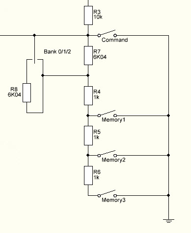
I decided that I have to make another K3NG keyer, this time full featured in order to test some things. Therefore, I started to make it "real" not just a breadboard full of "dead bugs". Looking into the code, I found a very interesting feature that provide 9 memories with only 3 buttons. The solution is proposed by Dietmar, DL2SBA and consist in both hardware and software modifications of the original source code (which is already big and full of stuff).
Choosing to have Command Buttons AND DL2SBA bankswitch resulted into error.
I gave it a shot and when Command Buttons feature and DL2SBA bankswitch feature are selected, the compiling ends into "exit status 1 invalid preprocessing directive #elseif" somewhere around the line #8632...
Therefore, I commented the bankswitch and get to my workaround! And this is my solution, below.
It's just a "shift" of the voltages read by the ADC; each position of the switch is "moving" the voltage with 3 memory places. Therefore, we have the same 3 banks but with no software hassle. Just check to see if in the "keyer_settings.h" there are at least 10 buttons (1 COMMAND and 9 memory).
Basically, my solution is similar to what Dieter proposed but it uses the original code without rewrite the variables on the ADC array. And gave no compile errors, of course. 73!