|
| Finally, a portable duplex UHF repeater! |
The first condition was to be imune to spurious signals from other transmitters because in a real emergency, is presumed that on the air will be a lot of activity.
Another crucial condition was the ability to operate from a lead acid battery for a long period of time, at leas for 12-24 hrs, depending on the alternative power supply at the site of the repeater. But to be sure, a period of time of 24 hrs was considered.
Based on my experience with various radios, "the chosen one" was the small GP300 from Motorola.
Why?
Hmmm, because:
-On the receiving it has a smart PLL demodulator able to improve considerably the S/N ratio, making faint signals receivable;
-The receiving front end is absolutely imune to adiacent and unwanted signals, opening the squelch only on a signal on the right frequency; this happens also when you put it on a high gain external antenna!
-The transmitter is self-aware about the temperature and pretty resistant to high SWR
-The modulation is extremly well done with a great AGC
-The current consumption on standby is around 30 mA while the TX current is around 1.7A @ 5W (very efficient!)
Also, Motorola GP300 has a long history of reliability in various conditions and, very important, the inner built is very strong and has a good EM shield around the PCB.
And the last, they have a nice and clean schematic and is a pleasure to work with a very few components for a good repeater! This is the condition of reliability!
The only con I found is the power supply; the radio itself work at 7.5V and the batteries usually at 12-14 V. A DC-DC converter is needed!
A couple of years ago I bought a small UHF duplex filter from a fellow ham. It's a 5 cell filter, with 2 cells on the low side and 3 cells on the high side. Of course, the receiving path of the repeater had to be on the upper side to have a better notch on the TX signal from the repeater itself.
The years gone by and recently, due to the increase interest in emergency communications, I started to think very serious about this forgotten project.
After a little search on the swap lists, I found two of them. Well, the versions I found are the narrow FM ones. I do have the filters for 25 kHz but is a pain in the s@&%#$ to change them so I decided to work with them instead of working against...
I did some modifications; the main mod is removing all the connectors form the top of the radio! The RF port, and the combined Earphon/Microphone. They take a lot of space! I also cut the shafts from the volume potentiometer and the channel selector... They are useles... Oh, don't forget to put the radio ON because after the shaft is cut, is very hard to do it!
Receiving side

From the receiver radio, we basically need only to signals:
- de-emphasised audio
- Carrier/PL detect
Take a look on the schematic. The audio will be taken after Q406 and after the C433, directly at the volume potentiometer. The main advantage is that the audio is muted! What does mean? Simple, the uC send a positive voltage to the Base of Q406 when a signal greater than the designated squelch level is received. Immediatly after the signal is gone, the receiving audio is muted, hence the white noise is suppressed. The repeater will not have a white noise tail! If you like to have it, just take the audio with a capacitor from the emitter of Q406. Is a little hard to find but not impossible if you have the service manual. (which, like other Motorola radios, I do not have, do not insist, search engines are your best friend!)
If you plan to play around with the audio and to extract the PL to work with on an external decoder, well, the things are a little bit complicated because you have to access the pin #7 of the AFIC circuit or pin # 28 of the Rx circuit (a modified topography of the classic MC3363). If you have the guts, you can connect to the uC pin # 41 where you have a nice digital signal extracted by AFIC, ready to b processed wherever you want!
You also can use the radio's low speed data slicer if you plan to use PL/DPL (CTCSS/DCS) to controll the repeater behaviour but I advice you to not because is hard to access the pins there! They are just near the uC chip.
Ok, so now we need a Carrier Detect signal. The carrier detect also cand work as a PL detect but only for the PL programmed in the radio's memory. If you need a PL, put it on the receiving side GP-300 and, voila! The repeater now open only at the right PL (CTCSS) or DPL (DCS)!
I took this signal directly from the Audio PA Vcc, U409 at pin # 1. There you will find the 7.5V when the radio receive a coherent signal.
Be aware, that path is open also when the radio want to send audio signals to the operator (battery low or other stuff like that).
By the way, I disabled all this signalling from the RSS.
Transmitting side
 The receiving signal from the other GP-300 will be "prepared" a little and after that, will be sent to the Mic input of the radio. Of course, due to the removal of the Mic connector, you will have to find the right pin on the PCB. Just put the radio into transmission and test the PCB holes where the connector was with a fine metal tip. On a control radio you will find the right pin very easy!
For the "engineers", take a look into the service manual and find C427... There you are!
The PTT is easy, just take a small piece of wire in parallel with the little switch on the left side of the radio. The lowest one. The PTT works when is put to the Ground and is tied up to 5V via a 10 kOhm resistor.
The controller

But provided a helpfull hand to test the repeater and the filter.
The second (and final) version was made around an Arduino Nano board.
The things were a little complicated because I want to have some sort of battery voltage indication to know when to shorten the QSOs.
 And the solution was very simple. I measure the battery voltage before the DC/DC converter and change the courtesy tone structure according to the battery state.
A single high pitch short beep when the voltage is between 11.5-13.8 V, a low pitch followed by a high pitch when the battery voltage is over the 13.8V, a high pitch followe by a low pitch when the voltage drop under 11.5 V and is higher than 10.5V and a long and grave beep when is even lower.
Under 10V, I plan to put a latch relay to close the radios. Or to block the PTT command signal. I don't know yet...
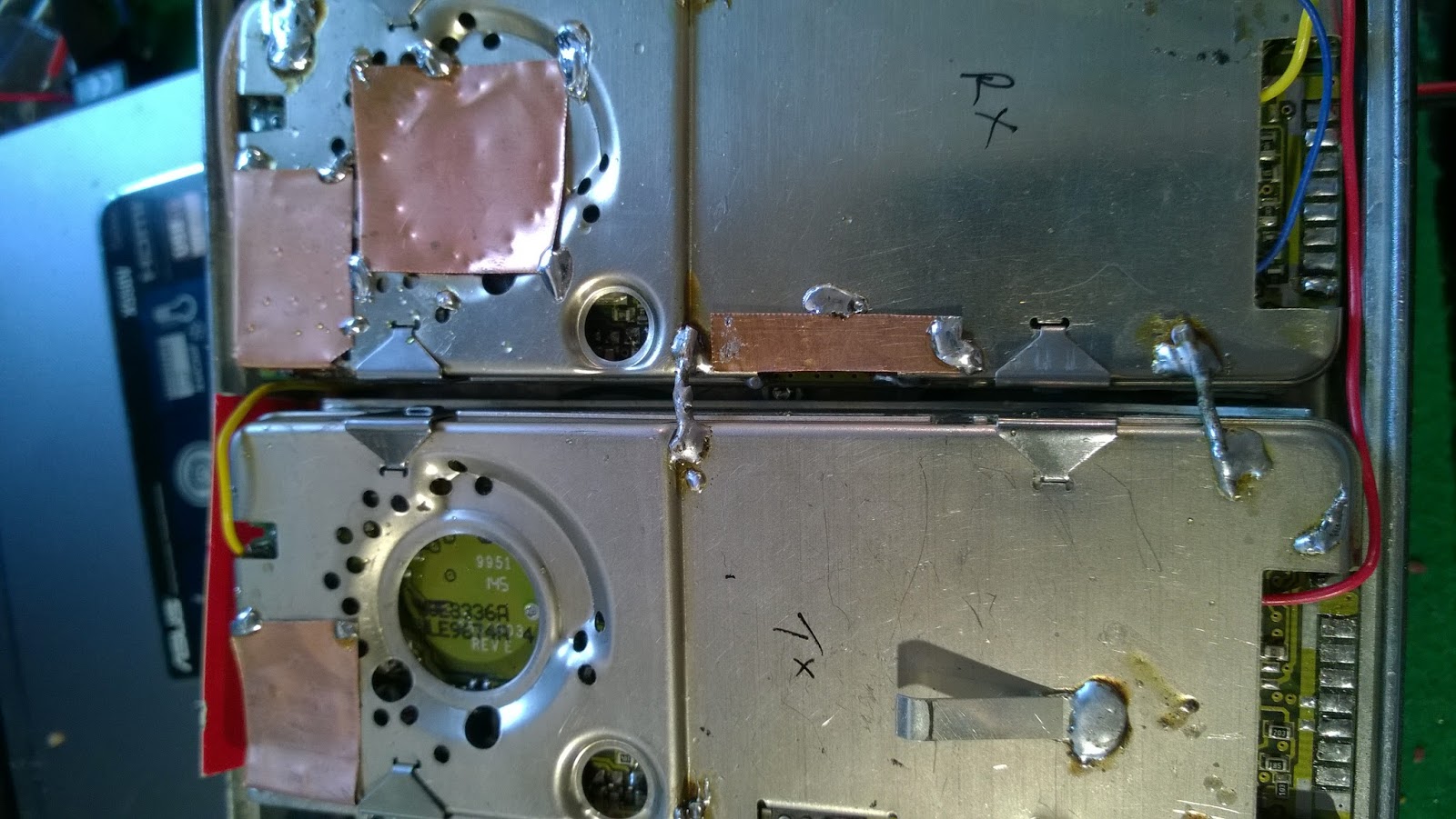
I found that the repeater has some noise and, after checking the duplex filter I concluded that the noise is internall. Indeed, after I took some drastic measures to ground the radios and to shield the receiving radio, the received signal is very clean and pleasant.
Of course, the repeater have a beacon which transmit the callsign, the QTH and the CTCSS if it is provided.
 |
| First setup. Some will say is ugly. I agree! |

 |
| Very quick PCB. Drawed by hand. |
 |
| A little bit of Arduino Nano... |

 |
| The conroller is assembled. |
 |
| The little UHF Repeater. |


 |
| Some more shielding. |

The code is on Github because here will be a mess:
https://github.com/yo3hjv/Arduino-Repeater-controller/blob/master/README.md