For some time I wanted to put LED DRL (Day Running Lights) on my car.
It was some pain in the a*** to run the wires into the car and I was looking for a simple and elegant solution.
And I was hit by inspiration!
I found the solution!
A DRL which power ON at the engine start and goes OFF a few minutes after the engine is stopped!
But how?
Simple, with an Arduino we test the battery voltage and decide to go ON or OFF because the lead-acid car battery goes under 12.8 V when the engine is stopped and above 13.4 when the engine is running!
Here is the code:
05 January 2020
22 July 2019
New Winlink CMS rules
All,
If you are a US-licensed station that routinely connects to a foreign gateway, or a non-US-licensed station that connects with a US gateway, you may be affected by new CMS behavior. The Winlink CMS now will enforce US Third-Party Message rules.
Because Winlink is being severely criticized for allowing US client and gateway operators to violate US amateur radio third-party traffic rules, we are today starting to test automatic enforcement of these rules. Part 97.3(47), 97.115 and 97.117 apply.
If you attempt to send or receive a third-party message between a US-licensed station and another station the US does not have a third-party communication agreement with, you may receive a service message saying the message will violate the applcable rules and that the message is refused (if you're sending) or being held at the CMS (if you are receiving). Alternative means to successfully send or receive the message will be explained. The US has treaties with most countries in the North and South America, but not most European, Asian and Pacific countries.
If you are a US-licensee, you should have no trouble sending and receiving to/from internet addresses if you connect with another US-licensed gateway, or one licensed in Central or South America — as long as the US has a third-party agreement with the licensing country.
If you are a non-US licensee, you should have no trouble sending and receiving to/from internet addresses if you connect to non-US licensed gateways.
We wish this was not necessary, but we have relied on US client and gateway operators to know the rules and obey them—and most have ignored them, unfortunately for all of us. In order to clean up the violations we are taking these measures to keep US Winlink operators legal. All licensees have an obligation to study, know, and obey the Amateur Radio Rules.
New monitoring and enforcement measures are coming into play with the establishment of a new Volunteer Monitor Program, now being set up by the ARRL at the request of the US FCC. We're doing this to make it easier for US operators to avoid loosing their licenses!
We will be tweaking the behavior of this new mechanism to make it as friendly and informative as it can be. Please bear with us as we make changes.
Thanks and 73,
Lor W3QA
Winlink Development Team
19 June 2019
1-10W QRP SWR meter

Pentru ca m-am hotarat sa reiau operarea din portabil QRP am nevoie de un instrument minimalist, usor si sigur care sa imi indice acordul antenelor.
Sigur, acum totul se face cu analizoare, care mai de care mai complexe si sofisticate. Am cateva insa sunt destul de incomode daca vrei sa iti incapa totul intr-un mic rucsac.
Asa ca m-am indreptat spre puntile SWR "clasice", realizate cu toroid.
Dupa mai multe experimente, am ajuns la solutia prezentata mai jos.

Nu am avut la indemana doua toruri asa ca am folosit un miez binocular, BN-43-2402 pe care am realizat ambele transformatoare.

Diodele pot fi de orice tip, Schottky; am avut la indemana BAT54.
Indicatia se face pe miliampermetru cu cap de scala 100uA. La 5W este cap de scala, fiind foarte sensibil. Am testat pe gama 1-30 MHz iar indicatia este potrivita pentru acordul cu precizie al antenei.
Miliampermetrele pot fi inlocuite cu doua LED-uri; preferabil verzi sau galbene, caz in care este nevoie de o baterie de 1,5V instalata conform linie punctate. Bateria poate fi lasata in circuit intrucat, in absenta semnalului de masurat, pragul de deschidere al LED-urilor nu este atins.
Daca se folosesc LED-uri, rezistentele Rs vor fi inlocuite cu unele de 10-15 Ohm.
Valorile indicate sunt pentru operare QRP, rezistentele fiind 0,25W. In cazul in care se doreste extinderea gamei la 100W, rezistentele de 47 Ohm vor fi inlocuite cu doua rezistente de 100 Ohm/0,5W, in paralel (am testat si la 100W si nu sunt probleme daca se utilizeaza serii scurte de emisie).
Atentie, la realizarea transformatorului infasurarile de 10 spire se vor bobina IN ACELASI SENS iar capetele care se conecteaza la sasiu vor fi intocmai ca in schema electrica!
Incercati sa realizati montajul cat mai simetric si cu plan de masa unitar iar rezultatele vor fi excelente!
Montajul poate fi utilizat pentru masurarea cu doua circuite AD8307 caz in care semnalul se va prelua direct de pe rezistentele de 47 Ohm.
Circuitul este reversibil; nu conteaza care este intrarea dar, in cazul in care il conectati invers, semnificatia LED-urilor se schimba si ea.
De altfel, reversibilitatea este folositoare la testarea rapida a realizari corecte.
Pe o sarcina de 50 Ohm, doar LED-url de FWD va lumina la aplicarea semnalului.
Inversand montajul, tot pe sarcina artificiala, va lumina LED-ul de SWR.
Daca efectuati acest test cu doua miliampermetre identice, veti observa mult mai usor functionarea corecta.
In varianta mea constructiva am folosit un combo de ace indicatoare incrucisate si am introdus in schema si un potentiometru pentru a putea modifica capatul de scala in functie de puterea statiei.
Succes!


| 50 Ohm resistive load | ||||||||||||||
| Ip. A | L | 1W | 2W | 3W | 4W | 5W | 6W | 7W | 8W | 9W | 10W | |||
| Rf in la Rf in | ||||||||||||||
| correct | a | SWR port | 0.900 | 6.000 | 9.000 | 15.700 | 23.000 | 32.800 | 47.800 | 55.600 | 63.000 | 78.500 | 95 | mV |
| b | PWR port | 0.21 | 0.48 | 0.75 | 0.92 | 1.10 | 1.30 | 1.49 | 1.68 | 1.92 | 2.12 | 2.45 | V | |
| Ip B | RfIn la ANT | |||||||||||||
| revers | a | SWR port | 0.21 | 0.60 | 0.77 | 1.00 | 1.19 | 1.37 | 1.57 | 1.80 | 1.98 | 2.22 | 2.44 | V |
| b | PWR port | 14.000 | 40.700 | 58.300 | 76.000 | 98.000 | 117.500 | 137.400 | 156.000 | 176.400 | 195.000 | 217 | mV |
13 June 2019

12 June 2019
COF-50
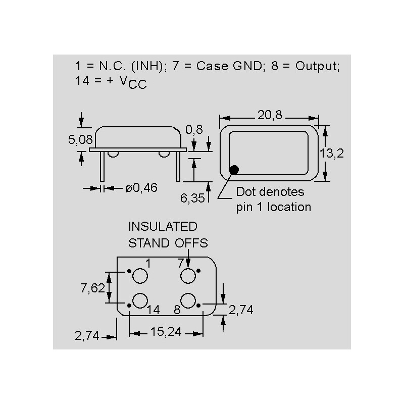
crystal oscillators
• in metal housing
• housing: DIL14
• frequence: 1...100MHz
• consisting of piezoelectric resonator and oscillator circuit
• high reliability due to hermetically sealed metal housing
• operating temperature range: 0...+70°C
• suitable for CMOS and TTL
• frequency range: 1.843 to 64 MHz
• by Abundance
• frequency stability: ±100ppm
• operating voltage (VDD):5 Volt DC
• current requirement, max.
1,843 to 20 MHz: 20 mA
24 to 40 MHz: 30 mA
50 MHz: 60mA
• symmetry at 50% VDD tight: 45 to 55%
• output voltage, max.
1"-Level: +4,5V(90% VDD)
"0"-Level: +0,5V(10% VDD)
• output load: 15pF typ. or 10 TTL max.
| Abundance |
| COF-8M-100-5V |
| DIL14 |
Subscribe to:
Posts (Atom)
Most viewed posts in last 30 days
-
 I will try to post here faults from various sources and how the problems were mitigated. The post will be periodically updated. Last updat...
 -
Finally, the schematic of Xiegu G90 is available! Here they are, in pdf format. 1 PA RF Board 2 Small Signal Board 3 Display Unit 4 Microph...
-
Kenwood Programing Software FIRMWARE: KDS-100 504XXXXX 4A46 PTT ID Display feature 176.86 KB CURRENT 401XXXXX F7FC Corrects lock up whe...