Pin 1 (Key) connects to the Tip of 3.5 mm Stereo Phone Plug.
Pin 2 (Start) connects to the Ring of 3.5 mm Stereo Phone Plug.
Pin 3 (+13.8V) connects to the Center Pin of Power Plug.
Pin 4 (Ground) connects to the Sleeves of both 3.5 mm Stereo Phone Plug and Power Plug.
05 May 2020
27 April 2020
K3NG keyer error with DL2SBA bankswitch mod
I decided that I have to make another K3NG keyer, this time full featured in order to test some things.
Therefore, I started to make it "real" not just a breadboard full of "dead bugs".
Looking into the code, I found a very interesting feature that provide 9 memories with only 3 buttons.
The solution is proposed by Dietmar, DL2SBA and consist in both hardware and software modifications of the original source code (which is already big and full of stuff).
Choosing to have Command Buttons AND DL2SBA bankswitch resulted into error.
I gave it a shot and when Command Buttons feature and DL2SBA bankswitch feature are selected, the compiling ends into
"exit status 1
invalid preprocessing directive #elseif"
somewhere around the line #8632...


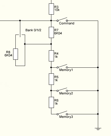
Therefore, I commented the bankswitch and get to my workaround!
And this is my solution, below.

It's just a "shift" of the voltages read by the ADC; each position of the switch is "moving" the voltage with 3 memory places.
Therefore, we have the same 3 banks but with no software hassle.
Just check to see if in the "keyer_settings.h" there are at least 10 buttons (1 COMMAND and 9 memory).

Basically, my solution is similar to what Dieter proposed but it uses the original code without rewrite the variables on the ADC array.
And gave no compile errors, of course.
73!
Therefore, I started to make it "real" not just a breadboard full of "dead bugs".
Looking into the code, I found a very interesting feature that provide 9 memories with only 3 buttons.
The solution is proposed by Dietmar, DL2SBA and consist in both hardware and software modifications of the original source code (which is already big and full of stuff).

Choosing to have Command Buttons AND DL2SBA bankswitch resulted into error.
I gave it a shot and when Command Buttons feature and DL2SBA bankswitch feature are selected, the compiling ends into
"exit status 1
invalid preprocessing directive #elseif"
somewhere around the line #8632...


Therefore, I commented the bankswitch and get to my workaround!
And this is my solution, below.

It's just a "shift" of the voltages read by the ADC; each position of the switch is "moving" the voltage with 3 memory places.
Therefore, we have the same 3 banks but with no software hassle.
Just check to see if in the "keyer_settings.h" there are at least 10 buttons (1 COMMAND and 9 memory).

Basically, my solution is similar to what Dieter proposed but it uses the original code without rewrite the variables on the ADC array.
And gave no compile errors, of course.
73!
10 April 2020
CW and Voice memory keyer for ICOM IC-7300
After a long time I decided to came back to CW.

Just for fun and to use the Pandemia holiday I thought will be interesting to have a little remote for the Voice and CW memory.
While the Voice memory callback is relatively simple with CI-V protocol, for CW memory there are no commands provided by ICOM.
Therefore, the keyer will store the preset messages (10 messages) and send them using a 4 x 4 keypad.
The uC of choice is an Arduino with Atmega 328 on UNO platform.
The keypad is also used to Power On and OFF the radio and TUNE the ATU (I use an AH-4).
The 4 x 4 keypad is able to send: -In CW, 10 preprogrammed CW messages, each of 128 bytes; -in SSB, AM, FM, 8 prerecorded voice messages -"A" is Power ON -"B" is Power OFF -"C" is TUNE
Here is a small video on youtube about this
Here is the code
08 April 2020
Triggering preset Voice memories and CW Memories on IC-7300
1. Voice memory M1 - M8
The PC send to the radio the following:
$FE $FE $to $from $28 $00 $## $FD
## - Memory Location
2. CW Memory M1 - M8
It cannot be sent directly by a dedicated command via CI-V. (found it hard way, confirmed HERE)
Therefore, a workaround can be done like this:
1. Read the memory by sending
$FE $FE $DEV $RADIO $1A $02 $## $FD (## 1 to 8)
the radio will respond with byte string
$FE $FE $DEV $RADIO $1A $02 ____ 70 bytes $FD

2. Load the bytes into an Array
Mem1[77] ; The Array will have 6 bytes preamble, 70 bytes message, 1 byte STOP BYTE (EOM)
3. For (int i = 6, i<=76, i++)
{ byte CW = Mem1[i];
sendPreable();
sendCW();
mySerial.write(CW);
sendSTOP();
}
This will send the stored message.
06 April 2020
ICOM CI-V IC 7300 commands
Here are some finding:
-All end on $FD
1C 01 00 - tuner OFF
-All end on $FD
Send CW characters
| $FE | $FE | ra | $E0 | $17 | $xx | $FD |
Tuner On/Off
$FE | $FE | ra | $E0 | $1C | $01 | $01 | $FD |
1C 01 01 - tuner ON
1C 01 02 - TUNE START
Delta TX On/Off
| $FE | $FE | to | fm | $05 | $21 | $00 | $08 | $13 | $01 |
BCD format / LSB first
Ex: $21 $00 $08 $13 $01 is dTX -1.308
Voice Memory Keyer
| $FE | $FE | to | fm | $28 | $## | $FD |
## - Memory slot
CW Memory Keyer
| $FE | $FE | to | fm | $1A | $05 | $01 | $56 | $## | $FD |
## - Memory slot
For 1.30 FW revision:

For 1.30 FW revision:

Subscribe to:
Posts (Atom)
Most viewed posts in last 30 days
-
 I will try to post here faults from various sources and how the problems were mitigated. The post will be periodically updated. Last updat...
 -
Finally, the schematic of Xiegu G90 is available! Here they are, in pdf format. 1 PA RF Board 2 Small Signal Board 3 Display Unit 4 Microph...
-
Kenwood Programing Software FIRMWARE: KDS-100 504XXXXX 4A46 PTT ID Display feature 176.86 KB CURRENT 401XXXXX F7FC Corrects lock up whe...