Well, I have a Kenwood Automatic antenna tuner AT-300 and some ICOM Radios (IC-7300 and IC-703+) and I want to use them.
I tried to find on internet something already made but no chance. Looks like the Kenwood AT-300 is very rare or the fellow hams are using it as is intended, with a Kenwood radio.
It's not my case so, after a couple of years of thinking, I put myself together and I start to explore the possible solutions to connect the ATU to my IC-7300 radio.
First, the radio has a START and a KEY line and the "0" logic is +5V and the '1" logic is 0V. Same as the AT-300 which is good. The Kenwood AT-300 has the same voltage logic but the signals are TS and TT.
Basically, the Kenwood tuning procedure is:
-The TUNE on the radio is pressed
-The radio pulls down the TS line
AND start transmitting around 10W CW.
-The AT-300 respond by pulling the TT down after about 100 msec.
ONLY IF RF IS PRESENT.
-If a tuning solution is found, the tuning stops and the TS line is pulled up to 5V.
-After 15 seconds, the radio stops the RF and pulls up the TS.
-If the TT is still up, the radio return TUNING ERROR. If the TT pulls up BEFORE the TS, the radio show TUNED.
For bypass, the TS is pulled down for 500 msec. WITHOUT RF. To put the tuner in circuit, repeat this sequence.
The ICOM radios, have a slighty different "tuning protocol":
-The radio pulls down the START line.
-The tuner pulls down the KEY,
causing the radio to transmit 10 W CW
-If the tuner found a tuning solution, the KEY is pulled up. From what I found using the Codan 9350 antenna, there is no time limit for keying the radio!
-If there is no tuning solution, the KEY is pulled up, then down for 70 msec. and then up again (and rest up).
The solution seems that is to "alter" the KEY and TS sequence with a microcontroller (Arduino).
Something like this:
-Press TUNE on the radio
-The radio pull down START
-The uC detect the START and pull down TS
-uC pull down KEY to transmit 10W CW
-uC monitors TT and pull up the KEY if the TT goes UP.
-If TT is still down after 15 seconds, the uC execute "TUNE FAIL" sequence as expected by ICOM radios.

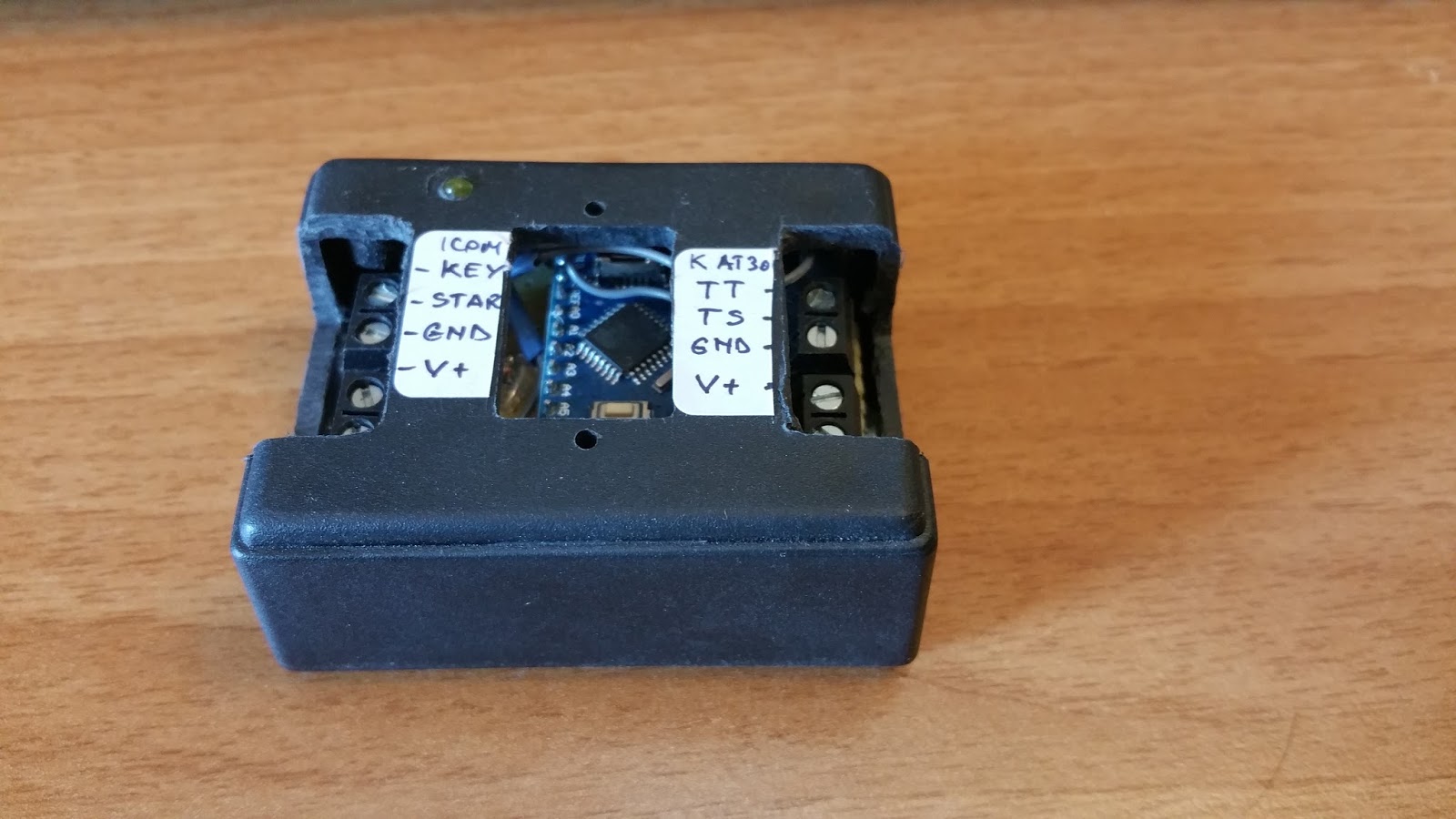
Already made the test board. initially i thought to put some optocouplers for TS/TT and START KEY but after monitoring the voltages I saw no problem to connect them directly to the Arduino digital ports (max 5V). Of course, the signal lines are connected through some 470 nH inductors and the uC pins have 10 nF capacitors to the ground.
I believe this interface will be good to use it also on IC-7000 (have one and i will test it) and IC-7100.
Stay "tuned" for the next step!
73 de Adrian YO3HJV
LATER EDIT
Here is the first version of the code. Simple tuning, start and stops at the TUNE command from the Radio front panel command.
About the hardware:
The lines are directly connected to the Arduino board and the lines from the ICOM radios are tied up to +5V with 4k7 resistors in order for the radio to "see" the external ATU!
Be aware that, if the output power is not set to be between 5-15W, the radio will turne to the INTERNAL ATU instead of the external, even with the lines pulled UP!


 Already made the test board. initially i thought to put some optocouplers for TS/TT and START KEY but after monitoring the voltages I saw no problem to connect them directly to the Arduino digital ports (max 5V). Of course, the signal lines are connected through some 470 nH inductors and the uC pins have 10 nF capacitors to the ground.


