During the years of use of my Kenwood TH-D74 I noticed that the battery indicator is a little bit confusing.
I never knew precisely how much "juice" I had in the battery from what the radio show on the LCD indicator.
So, being a brave ham I decided to put some clips on the battery contacts and make some measurements and correlate them with that little icon on the upper right side of the screen.
Under 7.2V:
7.2V - 7.4V
7.4V - 8.0V
8.0 V - 8.4V
Between 7.2 and 7.3V, the battery indicator is changing the colour from red to green.
The observation was made with the voltage going from 8.4V to 5.5V - the lowest voltage for which the radio is still working.
Having the radio already connected to my smart power supply, I thought it is the right occasion to make some measurements for the current draw in various configurations.
Here they are...
-GPS OFF
-Battery Save OFF
-SQ ON
-TNC OFF
VFO A: 160 mA
VFO B: 168 mA
VFO A + VFO B: 205 mA
VFO A + VFO B, SQ ON, vol@1/2: 270 mA
FM Radio ON: 210 mA
SD Rec ON: +15 mA
GPS ON: +30 mA
TNC ON: +~ 2mA
What about when transmitting?
Well, here they are, also:
EL (Extra Low)
VHF: 465 mA
UHF: 401 mA
L (Low)
VHF: 775 mA
UHF: 708 mA
M (Medium)
VHF: 1060 mA
UHF: 990 mA
H (High)
VHF: 1868 mA
UHF: 1920 mA
I want to stress out that these values are determined against my radio and can vary on others.
I do have an old Soviet "green
radio" R-109m which can cover 21.5 to 28.5 MHz which makes it pretty
attractive for playing in the field spooking CB-users :-)
But, a big problem on those old radios are the batteries; they used two sets of NHK-14 each consisting in two batteries in series to get + and - 2.4V.
Since I got this radio I used a simple common ground divider and a 6V/6Ah Lead battery but the big problem is easy to spot: the battery will be quick depleted by the current that goes through the resistors.
(this schematic is from here: https://www.greenradio.de/e_schalt.htm).
I tried to find on Chinese sites a module that can convert a voltage between 9-15V to +/- 2.4V with common ground but I couldn't find one and I did this through an extensive period of time, around 10 years.
So, being a brave ham, the next logical step was to make my own power supply...
While doing one with linear regulators like LM317 / LM337 could solve the job, the power dissipation would make them unsuitable, being just an expensive version of resistor board I tried first.
Another solution would be to use one LiIon/LiPo cell per each power line (one for positive, one for negative with common ground) but those cells have +4.2V when full charge and that could be too much for the transistor-based DC/DC converter that is built in in these radios!
I now that first hand, I took out the smoke from a few of them when I was in the army!
If we take a look at the internal SMPS of this radio, we see that there is no feedback loop to regulate the output; the engineers assumed that only the proper batteries will be used.
Also, the voltage from the batteries is going to various places in the radio so the positive and negative rails will have different currents so each one must be maintained under 2.4V.
So, with the help of a few nice people that offered some valued advices, I made my first Switched Mode Power Supply from scratch.
Of course, the first iteration didn't get too well; ita failed to keep both voltages well regulated when I draw a bigger current on one of the lines, so I had to made a second one.
This time, everything went perfect!
The PCB's looks awesome. I ordered 5 pcs.!
I made three of them because I have two hams here that want this too...
It fits.
... and it's works too!
Next step will be to make a proper case to put the fuse, the switch and so on.
Some specs:
-Frequency: 50 KHz (+/- 5%)
-Tested input supply voltage: 7.5 to 17V.
-Input recommended voltage: 10 to 17V.
-Current draw when no load attached: 4mA
-Observed efficiency: better than 90%.
-Output voltage (settable): +/- 1.4V to +/- 5V.
-Max, Output current: 2x 2.5A for short periods, 2x 1.5A sustained.
I did some tests at 100 KHz and it is working well too and, by choosing the right capacitors, a +/- 12V can be achieved without any problems, making it a nice power supply for other old "green radios".
Important thing is that now, I can power my military radio from a large range of batteries, from RC LiIon packs to car battery!
Here is the temperature after some time in a stress test.
Input: 13V
Current: 2.5A.
No radiators.
By choosing the right wiring of the transformer and cooling, the SMPS can be used to power a broader range of radios with higher current or higher voltage (with right capacitors in the secondary circuit).
Waiting for the case, I bent an aluminium strip and made a little radiator and did some stress test for a longer time.
Gate signal in blue trace and Drain signal in yellow trace.
Powered by 13.2V and 2.5A on each rail in respect to the common ground, I let it run for 2 hrs.
The only problem was the smell from the resistors...
Here are some thermal camera pics:
Overall:
Load:
Transistors:
Diodes:
Chokes:
So, after a painfull process of learning some elements of CAD I did some sort of a case, and sent it to a small factory to cut the aluminium and bend it on some machines...
And i wait, and I wait but finally, today they came!
Well, after testing a lot of ESP32 development boards, I found that the little ESP32 D1 Mini is an excellent one.
First of all, it is very fast when programming!
Second, you don't have to fuss around with pressing BOOT, EN/RST or other complicated procedures!
Third, never, but never the programming stopped due to communication errors (like a lot of DevKit boards).
The single inconvenient I can found, and is a big one, is the dual rows of pins!
They are hard to access, I always misread the labels because they are very crammed and I found stupid to have them on the back of the board, but this is, of course, because there is no space on the upper side.
Anyway, you get the ideea: very good boards but pretty hard to use Dupont wires to test various hardware with them.
So, I was looking to an expansion board for Arduino Nano and asked myself if I can find a similar board for D1 Mini! Back in the old days when i start with Arduino (and Nano was a cheap thing) this expansion board was a gem and help me with a lot of projects....
So, I searched for a similar one but all that I found were little boards with some sh$%# on them, none being what I was really needed!
But then, I asked myself, "why not MAKING one"?
First step is to make a PLAN! What are my expectations? How do I mostly use this dev boards? What accessories I often use?
So, the requirements were written on a paper:
-Power supply from a various sources; both from USB and from external 6-20V.
-Multiple I2C configured to use I2C LCD with SCL, SDA, +, GND.
-I2C for 3V3 and 5V accessories.
-Every GPIO to have it's 3V3 and GND pins near for easy wiring.
-If the board is external powered, the regulated voltages to be available for other accessories.
-Multiple SPI.
-Accessible UART for ... things...
Using EasyEDA I made the schematic:
... and while waiting for the boards ordered in China, I also ordered the components.
Well, yeah, a close inspection will reveal that I made a mistake with the coaxial power Jack... I wired the wrong pin to Vcc :-( but the cutter fixed the little annoyance.
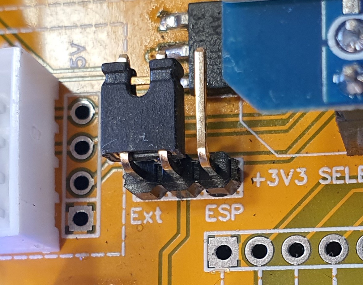
The 3V3 can be selected from the external power supply or from the ESP regulator:
I have two 3V3 I2C and two 5V I2C. Yes, i know the best practice is to have level translators but a 220 Ohm on each SDA and SCL will do the job very well...


.jpg)


