I heard this evening a shocking news! L.B. Cebik passed away! I am stoned! I use to chek weekely his web page for something new about antennas and NEC modelling. From now on, that page will show the same article. I am very sad about!
L.B. Cebik a murit in penultima saptamana din aprilie. A fost un adevarat guru al antenelor si mereu aveam cate ceva de descoperit pe site-ul sau web! Din pacate, munca sa a ramas neterminata, caci antenele sunt un domeniu infinit.
Odihneasca-se in pace!
08 May 2008
07 May 2008
Firefox crash under Vista Ultimate Business
I have not had any issues on the IE 7 stoppage, but when I click a link in
Firefox 2.0.0.11 that takes me to a page for a pop up or if i have to leave
that page I get the "Firefox has stopped working error". I already went to
2.0.0.12 but that did not fix it. Any fixes??
Thanks
The message was found on a forum. I have the same problem. My Firefox is updated at 2.0.0.13 and i'm using a Lenovo Thinkpad X61 Tablet.
By the way, i have some problems also with restoring after hibernation! The applications stops responding after waking from sleep or hibernation! Some people says that this is related to intel Turbo Memory. I remove it but it worked just for a few hibernation followed by waking. I tryied to remove some Thinkpad applications but nothing happens. I use the preinstalled system. I think I will try to install (clean install ) a Win XP Tablet edition.
03 May 2008
Interfata telefonica RDS<>145.225Mhz
In Bucuresti este activa o interfata telefonica radio la numarul 0314.21.66.28.
Frecventa de iesire a sistemului radio este 145.225, canalul de apel local.
Sistemul este bazat pe interfata CSI-Private Patch V si Motorola GP300 cu Pout de 6W.
Amplasarea este langa Palatul Parlamentului, acoperind cu un semnal satisfacator Bucurestiul.
Pentru a utiliza aceasta interfata, retineti urmatoarele:
-Cand va conectati la sistem, dupa semnalul normal de apel, in receptorul telefonic veti auzi un semnal continuu (ton) de aproximativ 1 secunda. Acest ton semnifica initializarea sistemului. Dupa acest semnal, veti auzi in receptorul telefonic QSO-urile in curs in banda radio.
-Sistemul este SIMPLEX si activat cu VOX in ambele directii; nu veti putea vorbi peste corespondentul din banda radio, asteptati sa termine ce are de spus; in timp ce vorbiti, daca faceti pauze mai lungi, sistemul va trece in receptie reintrand in emisie cand transmiteti informatie audio. Similar se petrec lucrurile si cand corespondentul radio face pauza in vorbire;
-Cand va aflati pe calea telefonica, inchideti statia radio aflata pe frecventa sistemului (cand va aflati in aria de acoperire radio) intrucat semnalul din difuzor va ajunge in microfonul telefonului si va cauza un efect de microfonie. Acest efect este dublat de ecou deoarece liniile telefonice folosesc procesari digitale care introduc o mica intarziere in semnal;
-Semnalizati terminarea reprizei de vorbire prin cuvantul "TERMINAT", astfel, corespondentul va sti ca poate intra in emisie;
-Identificati-va cand accesati prin telefon sistemul, desi vorbiti la un telefon, ceea ce spuneti se aude in banda radio, a carei utilizare este supusa unor reguli;
Nu abuzati de sistem cu probe si mitocanii, sistemul este supravegheat, convorbirile inregistrate si ID-ul apelantului stocat informatic.
Inregistrarea se face exclusiv pentru cazul in care este reclamata utilizarea neautorizata cu incalcarea Regulamentului de comunicatii de amator.
Intrucat se intentioneaza mentinerea in activitate a acestui sistem de comunicatie pentru uzul radioamatorilor, utilizarea neautorizata va face obiectul sesizarii ANRCTI.
Mai sta o perioada in probe, apoi va putea fi folosit bidirectional, adica se vor putea initia convorbiri telefonice si din calea radio.
HF+VHF / UHF Diplexer
The following DIPLEXER separates the following bands:
- HF and 6m on one side (= 0 - 52 Mc).
- 2m and 70cm on the other side.
It allows the simultaneous operation of 2 different equipments
(HF and VHF/UHF) over one coax cable, or the use of 2
antennas of the corresponding bands with one coax cable.
That means, you can operate on HF and listen or transmit at
the same time on VHF or UHF, all through the same coax cable.
It is also suitable to connect a 3 band antenna (uhf/vhf/6m) with
the antenna connectors of a transceiver as IC-706,
FT-100, or TS-2000 transceiver.
The following data was measured at 50 Ohm input and output:
- Attenuation of the other band is very high (over 60 db)
- Insertion loss is negligible (less than 0.2 db)
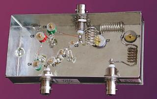
The circuit may be built easily into a metallic box measuring
abt. 11 cm x 5,5 cm x 3 cm.
Here's the circuit diagram:
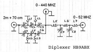
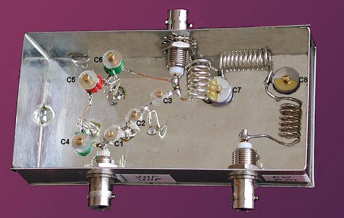
Component list: all coils 1mm dia enameled copper wire
L1 = 1 turn 5 mm (id)
L2 = same as L1, orientation 90 degr in respect to L1
L3 = 1 1/2 turn 6 mm (id)
L4 = same as L3 , orientation 90 degr in respect to L3
L5 = 7 turn 6 mm (id), 15 mm long
L6 = 11 turn 6 mm (id), 19 mm long
L7 = same as L5
C1 = foil trimmer cap. 9 pf (0.5-9 pf) see note in text
C2 = same as C1
C3 = same as C1
C4 = foil trimmer cap. 32 pf (3-32 pf)
C5 = same as C4 C6 = same as C4
C7 = foil trimmer cap. 135 pf (5-135 pf)
C8 = same as C7
3 HF chassis plugs 50 Ohm (BNC)
1 metallic box (solderable)
Coils may be made of silvered copper wire, but enameled
copper wire serves equally well.
The layout should be equal, otherwise undesired coupling
may occur which hinders proper operation.
Proper adjustment of the unit is very important.
This requires some time and patiance. Prior to adjustment,
make sure that the SWR meter is calibrated exactly for
all measuring frequencies and reads exactly 1.0 when
terminated by dummy load and make sure that
dummyload is 50 Ohm on each band.
Adjustment procedure:
1. Connect 50 Ohm dummyload to plug 0 - 440 MHZ .
2. Connect SWR meter between 0 - 52 MHZ plug and
TX (51 Mc carrier low power).
(If no 6m TX available adddjust on 10m band)
Adjust C7 and C8 to obtain SWR < 1.1 .
3. Connect SWR meter between 2 m plug and TX on 2 m
(145 Mc carrier low power). Adjust C4, C5, and C6 to obtain
SWR < 1.1 . C4 and C6 should reach the same value.
4. SWR meter same as step 3, but TX on 70 cm
(435 Mc carrier low power). Adjust C1, C2, and C3
to obtain SWR < 1.1 . C1 and C3 should reach the same
value.
- Repeat steps 2 - 4 , as adjustment of one band influences
the other. You will need some patience to reach proper
adjustment on all bands!
Now your diplexer is ready for use. If an antenna analyzer
(e.g. MFJ-269) is available, use this instead of the SWR meter
and TX to make adjustment more easy. Connect analyzer
to plug 0 - 440 MHZ and dummy load to plug being adjusted.
Note: Power is limited by the capacitors. Many foil capacitors
burn at low power. Some types are stronger.
With my trimmers I tested up to 100 w on HF and 6m,
and 50w on 2m and 70 cm.
Use capacitors with higher current/voltage ratings at
higher power, e.g. good air trimmer capacitors.
- HF and 6m on one side (= 0 - 52 Mc).
- 2m and 70cm on the other side.
It allows the simultaneous operation of 2 different equipments
(HF and VHF/UHF) over one coax cable, or the use of 2
antennas of the corresponding bands with one coax cable.
That means, you can operate on HF and listen or transmit at
the same time on VHF or UHF, all through the same coax cable.
It is also suitable to connect a 3 band antenna (uhf/vhf/6m) with
the antenna connectors of a transceiver as IC-706,
FT-100, or TS-2000 transceiver.
The following data was measured at 50 Ohm input and output:
- Attenuation of the other band is very high (over 60 db)
- Insertion loss is negligible (less than 0.2 db)
The circuit may be built easily into a metallic box measuring
abt. 11 cm x 5,5 cm x 3 cm.
Here's the circuit diagram:

Component list: all coils 1mm dia enameled copper wire
L1 = 1 turn 5 mm (id)
L2 = same as L1, orientation 90 degr in respect to L1
L3 = 1 1/2 turn 6 mm (id)
L4 = same as L3 , orientation 90 degr in respect to L3
L5 = 7 turn 6 mm (id), 15 mm long
L6 = 11 turn 6 mm (id), 19 mm long
L7 = same as L5
C1 = foil trimmer cap. 9 pf (0.5-9 pf) see note in text
C2 = same as C1
C3 = same as C1
C4 = foil trimmer cap. 32 pf (3-32 pf)
C5 = same as C4 C6 = same as C4
C7 = foil trimmer cap. 135 pf (5-135 pf)
C8 = same as C7
3 HF chassis plugs 50 Ohm (BNC)
1 metallic box (solderable)
Coils may be made of silvered copper wire, but enameled
copper wire serves equally well.
The layout should be equal, otherwise undesired coupling
may occur which hinders proper operation.
Proper adjustment of the unit is very important.
This requires some time and patiance. Prior to adjustment,
make sure that the SWR meter is calibrated exactly for
all measuring frequencies and reads exactly 1.0 when
terminated by dummy load and make sure that
dummyload is 50 Ohm on each band.
Adjustment procedure:
1. Connect 50 Ohm dummyload to plug 0 - 440 MHZ .
2. Connect SWR meter between 0 - 52 MHZ plug and
TX (51 Mc carrier low power).
(If no 6m TX available adddjust on 10m band)
Adjust C7 and C8 to obtain SWR < 1.1 .
3. Connect SWR meter between 2 m plug and TX on 2 m
(145 Mc carrier low power). Adjust C4, C5, and C6 to obtain
SWR < 1.1 . C4 and C6 should reach the same value.
4. SWR meter same as step 3, but TX on 70 cm
(435 Mc carrier low power). Adjust C1, C2, and C3
to obtain SWR < 1.1 . C1 and C3 should reach the same
value.
- Repeat steps 2 - 4 , as adjustment of one band influences
the other. You will need some patience to reach proper
adjustment on all bands!
Now your diplexer is ready for use. If an antenna analyzer
(e.g. MFJ-269) is available, use this instead of the SWR meter
and TX to make adjustment more easy. Connect analyzer
to plug 0 - 440 MHZ and dummy load to plug being adjusted.
Note: Power is limited by the capacitors. Many foil capacitors
burn at low power. Some types are stronger.
With my trimmers I tested up to 100 w on HF and 6m,
and 50w on 2m and 70 cm.
Use capacitors with higher current/voltage ratings at
higher power, e.g. good air trimmer capacitors.
Original article HERE
26 April 2008
Subscribe to:
Posts (Atom)
Most viewed posts in last 30 days
-
Despite the rumors, the Russian are not using Baofeng Two Way radios in Ukraine invasion. They are using more modern and advanced communicat...
-
I was playing with this circuit but the audio was crap. Looking into the circuit's datasheet I found that this is a real treasure by...
-
 Well, after testing a lot of ESP32 development boards, I found that the little ESP32 D1 Mini is an excellent one. First of all, it is ve...
