18 January 2015

CTCSS decoder with Arduino

From a friend of mine i got an ideea for a complex repeater controller, able to work with 4 radios. Two of them forming a UHF repeater and, at least, two other, forming a second repeater or simplex radios for linking the first repeater with other remote repeaters.
But this is not the subject here...


The first step was to check the possibility to decode CTCSS and to generate it back. But decoding was the biggest challenge.
I was looking for some CML circuits but the representative here asked me to buy a large quantity at a big price.
So I was turning to my Arduino trying to figure it out how to make it able to decode CTCSS in no more than 100 msec.
Finally, I did it by measuring the pulses between interrupts and find this method pretty nice and precise, at least for a crystal resonator driven Arduino.

*** Refinements of the initial code was further made by Jean-Jacques ON7EQ   and  Paul ON4ADI. Please, read to the end.


Here is the code, just copy/paste it in the Arduino IDE:
// Frequency counter sketch, for measuring frequencies low enough to execute an interrupt for each cycle
// Connect the frequency source to the INT0 pin (digital pin 2 on an Arduino Uno)
// By Adrian, YO3HJV
// This work is released to Public Domain
// First published on January, 18th 2015 on
// http://yo3hjv.blogspot.ro/2015/01/ctcss-decoder-with-arduino.html
// This code can be used for free but I will appreciate if you mention the author.
// 73 de Adrian, YO3HJV


#include
#include
/ *May be uncomment for standard Arduino LCD library.
I am using a weird library here... */
LiquidCrystal lcd(8, 9, 4, 5, 6, 7); // set for my configuration. Let PIN2 to be the input for the signal.
volatile unsigned long timpPrimImpuls;
volatile unsigned long timpUltimImpuls;
volatile unsigned long numImpuls;
void setup()
{
//Serial.begin(19200); // print for debugging. Uncomment if necessary
lcd.begin(16, 2);
}
// Measure the frequency over the specified sample time in milliseconds, returning the frequency in Hz
float readFrequency(unsigned int sampleTime)
{
numImpuls = 0; // start a new reading
attachInterrupt(0, counter, RISING); // enable the interrupt
delay(sampleTime);
detachInterrupt(0);
return (numImpuls < 3) ? 0 : (996500.0 * (float)(numImpuls - 2))/(float)(timpUltimImpuls - timpPrimImpuls);
}
// NOTE: 996500.0 is the value find by me. The theoretic value is "1000000000.0"
// Start with this value and check the precision against a good frequency meter.
void loop()
{
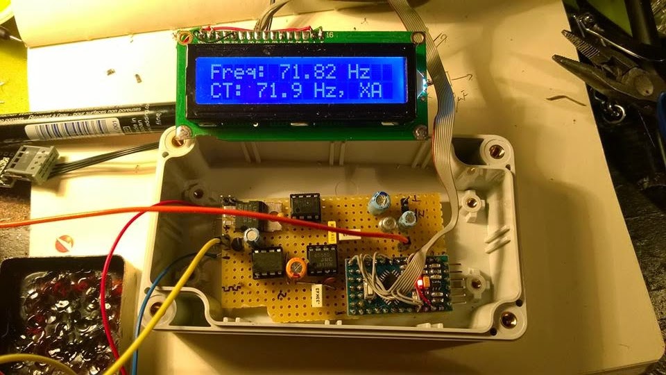
float freq = readFrequency(100);
lcd.setCursor(0, 0);
lcd.print("Freq: ");
lcd.print (freq);
lcd.print(" ");
lcd.print("Hz ");
lcd.setCursor (0, 1);
// Too low but over 10 Hz
if ((freq > 10) && (freq < 65.8))
{
lcd.print(" TOO LOW ");
//DO SOMETHING
}
else if ((freq > 66.00) && (freq < 68.00))
{
lcd.print("CT: 67.0 Hz, XZ ");
//DO SOMETHING
}
else if ((freq > 68.30) && (freq < 70.30))
{
lcd.print("CT: 69.3 Hz, WZ ");
//DO SOMETHING
}
else if ((freq > 70.90) && (freq < 72.90))
{
lcd.print("CT: 71.9 Hz, XA ");
//DO SOMETHING
}
else if ((freq > 73.40) && (freq < 75.40))
{
lcd.print("CT: 74.4 Hz, WA ");
//DO SOMETHING
}
else if ((freq > 76.00) && (freq < 78.00))
{
lcd.print("CT: 77.0 Hz, XB ");
//DO SOMETHING
}
else if ((freq > 78.70) && (freq < 79.70))
{
lcd.print("CT: 79.70 Hz, WB ");
//DO SOMETHING
}
else if ((freq > 81.50) && (freq < 83.50))
{
lcd.print("CT: 82.5 Hz, YZ ");
//DO SOMETHING
}
else if ((freq > 84.30) && (freq < 86.50))
{
lcd.print("CT: 85.4 Hz, YA ");
//DO SOMETHING
}
else if ((freq > 87.40) && (freq < 89.60))
{
lcd.print("CT: 88.5 Hz, YB ");
//DO SOMETHING
}
else if ((freq > 90.40) && (freq < 92.60))
{
lcd.print("CT: 91.5 Hz, ZZ ");
//DO SOMETHING
}
else if ((freq > 93.7) && (freq < 95.90))
{
lcd.print("CT: 94.8 Hz, ZA ");
//DO SOMETHING
}
else if ((freq > 96.30) && (freq < 98.5))
{
lcd.print("CT: 97.4 Hz, ZB ");
//DO SOMETHING
}
else if ((freq > 99.00) && (freq < 101.00))
{
lcd.print("CT: 100.0 Hz, 1Z ");
//DO SOMETHING
}
else if ((freq > 102.40) && (freq < 104.60))
{
lcd.print("CT: 103.5 Hz, 1A ");
//DO SOMETHING
}
else if ((freq > 106.10) && (freq < 108.30))
{
lcd.print("CT: 107.2 Hz, 1B ");
//DO SOMETHING
}
else if ((freq > 109.80) && (freq < 112.00))
{
lcd.print("CT: 110.9 Hz, 2Z ");
//DO SOMETHING
}
else if ((freq > 113.60) && (freq < 116.00))
{
lcd.print("CT: 114.8 Hz, 2A ");
//DO SOMETHING
}
else if ((freq > 117.60) && (freq < 119.90))
{
lcd.print("CT: 118.8 Hz, 2B ");
//DO SOMETHING
}
else if ((freq > 122.00) && (freq < 124.00))
{
lcd.print("CT: 123.0 Hz, 3Z ");
//DO SOMETHING
}
else if ((freq > 126.20) && (freq < 128.40))
{
lcd.print("CT: 127.3 Hz, 3A ");
}
else if ((freq > 130.40) && (freq < 133.00))
{
lcd.print("CT: 131.8 Hz, 3B ");
}
else if ((freq > 135.00) && (freq < 138.00))
{
lcd.print("CT: 136.5 Hz, 4Z ");
//DO SOMETHING
}
else if ((freq > 140.00) && (freq < 142.80))
{
lcd.print("CT: 141.3 Hz, 4A ");
//DO SOMETHING
}
else if ((freq > 145.00) && (freq < 147.80))
{
lcd.print("CT: 146.2 Hz, 4B ");
//DO SOMETHING
}
else if ((freq > 150.00) && (freq < 152.80))
{
lcd.print("CT: 151.4 Hz, 5Z ");
//DO SOMETHING
}
else if ((freq > 156.00) && (freq < 158.80))
{
lcd.print("CT: 157.7 Hz, 5A ");
//DO SOMETHING
}
// NON-STANDARD
else if ((freq > 159.00) && (freq < 161.00))
{
lcd.print("CT: 159.8 Hz, -- ");
//DO SOMETHING
}
else if ((freq > 161.00) && (freq < 163.50))
{
lcd.print("CT: 162.2 Hz, 5B ");
//DO SOMETHING
}
// NON-STANDARD
else if ((freq > 164.00) && (freq < 166.30))
{
lcd.print("CT: 165.5 Hz, -- ");
//DO SOMETHING
}
else if ((freq > 166.60) && (freq < 169.00))
{
lcd.print("CT: 167.9 Hz, 6Z ");
//DO SOMETHING
}
// NON-STANDARD
else if ((freq > 170.00) && (freq < 172.40))
{
lcd.print("CT: 171.3 Hz, -- ");
//DO SOMETHING
}
else if ((freq > 172.60) && (freq < 175.00))
{
lcd.print("CT: 173.8 Hz, 6A ");
//DO SOMETHING
}
//NON-STANDARD
else if ((freq > 176.00) && (freq < 178.50))
{
lcd.print("CT: 177.3 Hz, -- ");
//DO SOMETHING
}
else if ((freq > 178.6) && (freq < 181.00))
{
lcd.print("CT: 179.9 Hz, 6Z ");
//DO SOMETHING
}
//NON-STANDARD
else if ((freq > 182.00) && (freq < 184.80))
{
lcd.print("CT: 183.5 Hz, -- ");
//DO SOMETHING
}
else if ((freq > 185.00) && (freq < 187.50))
{
lcd.print("CT: 186.2 Hz, 7Z ");
//DO SOMETHING
}
//NON-STANRDARD
else if ((freq > 188.40) && (freq < 191.30))
{
lcd.print("CT: 189.9 Hz, -- ");
//DO SOMETHING
}
else if ((freq > 191.00) && (freq < 194.00))
{
lcd.print("CT: 192.8 Hz, 7A ");
//DO SOMETHING
}
//NON-STANDARD
else if ((freq > 195.40) && (freq < 198.00))
{
lcd.print("CT: 196.6 Hz, -- ");
//DO SOMETHING
}
//NON-STANDARD
else if ((freq > 198.30) && (freq < 201.00))
{
lcd.print("CT: 199.5 Hz, -- ");
//DO SOMETHING
}
else if ((freq > 202.00) && (freq < 204.00))
{
lcd.print("CT: 203.5 Hz, M1 ");
//DO SOMETHING
}
else if ((freq > 205.00) && (freq < 208.00))
{
lcd.print("CT: 206.5 Hz, 8Z ");
//DO SOMETHING
}
else if ((freq > 209) && (freq < 212.00))
{
lcd.print("CT: 210.7 Hz, M2 ");
//DO SOMETHING
}
else if ((freq > 217.00) && (freq < 219.30))
{
lcd.print("CT: 218.1 Hz, M3 ");
}
else if ((freq > 224.00) && (freq < 227.00))
{
lcd.print("CT: 225.7 Hz, M4 ");
}
else if ((freq > 227.60) && (freq < 231.30))
{
lcd.print("CT: 229.1 Hz, 9Z ");
//DO SOMETHING
}
else if ((freq > 231.70) && (freq < 235.00))
{
lcd.print("CT: 233.6 Hz, -- ");
//DO SOMETHING
}
else if ((freq > 239.60) && (freq < 243.00))
{
lcd.print("CT: 241.8 Hz, M6 ");
//DO SOMETHING
}
else if ((freq > 248.00) && (freq < 252.00))
{
lcd.print("CT: 250.3 Hz, M7 ");
//DO SOMETHING
}
else if ((freq > 252.70) && (freq < 256.80))
{
lcd.print("CT: 254.1 Hz, 0Z ");
//DO SOMETHING
}
else if (freq > 256.80)
{
lcd.print(" TOO HIGH ");
//DO SOMETHING
}
else
{
lcd.setCursor (0, 1);
lcd.print(" NOISE ");
// or, comment the line above and
// uncomment the line below for an empty LCD line
// lcd.print(" ");
}
delay(50);
// lcd.clear(); //Not necessary. uncomment but will flicker!
} //END OF LOOP
void counter()
{
unsigned long now = micros();
if (numImpuls == 1)
{
timpPrimImpuls = now;
}
else
{
timpUltimImpuls = now;
}
++numImpuls;
}


After fine tuning the code, the second issue was to make the Arduino read from real life signals, a.k.a from the discriminator (FM detector).
But there, unfortunately, there is also "noise" above 300 Hz from the voice and the Arduino will tend to detect it too, asuming that we have a 5Vpp signal on pin 2 of the UNO board.
Therefore, a preamplifier and a Low Pass Filter to cut all the frequencies below* above 260 Hz with at least 12db/octave.
I will not bother you with more than necessary details, I post the schematics here and if someone has questions i will answer.

73 de Adrian YO3HJV


A "Later Edit" is a must!
After some emails with Carlo IU1DOR found some mistakes in the schematics. One is about the parallel diodes at U3a which are drawn as conductive in one sense; must be corrected as anti-parallel diodes.
The second one is R10 which is not in series with that diodes.

Here is the original part from Motorola GM300 schematics:


Anyway, Carlo kindly give me the permission to post here the PCB layout for the filter (TNX!):


The code is available on GITHUB. 
*-TNX  IU1DOR for correction!

LATER EDIT  (15 feb. 2016)
I recently received a e-mail from Jean-Jacques ON7EQ   who pointed me to an upgrade to this project.
The upgrade was made possible by the work of Paul ON4ADI who refine the code and added a necessary software filter to make the CTCSS Arduino decoder able to withstand to real world conditions.
The project of the new CTCSS decoder can be seen here.


03 January 2015

Mini Meteo Station with Arduino Nano

I finished a complex project, a mini Meteo Station based on Arduino Nano.

On a 4x20 I2C LCD I can see the date, time, inside and outside temperature, relative humidity and air pressure (in hPa).


Main features are:
    -Low footprint
    -Precise Date and Time with a DS1307 RTC circuit
    -Humidity with a DHT-11 sensor
    -Baro pressure and interior temperature with a BMP-085
    -External temperature with a DS-18B20
    -Low power (40 mA from one Li-Ion cell with a DC-DC converter with LCD Backlight on, 30 mA).
    -LCD Backlight on demand by push button

Took me about 2 days but I made it!

I intend to make some averages and to compare the pressure over an variable inteval tohave a weather prediction.


Here is the code:


 /*

   Meteo station with Arduino Nano
   by Adrian, YO3HJV
   http://yo3hjv.blogspot.com


  -- LCD on I2C
  -- Barometer and temperature sensor BMP-085 on I2C
  -- Humidity sensor DHT-11 on pin D3
  -- Dallas DS-18B20 temperature sensor on OneWire, pin D2
  -- Backlight Push button on pin A3
 
  */


   #include <Wire.h>
   #include <LCD.h>
   #include <LiquidCrystal_I2C.h>
   #include <Time.h>
   #include <DS1307RTC.h>
   #include <Barometer.h>
   #include <OneWire.h>
   #include <DallasTemperature.h>
   #include <dht11.h>
  
                                          // Data wire is plugged into port 2 on the Arduino
    #define ONE_WIRE_BUS 2                                         
    OneWire oneWire(ONE_WIRE_BUS);                                       
    DallasTemperature sensors(&oneWire);
   
    #define DHT11PIN 3
   
    dht11 DHT11;


// I2C LCD DISPLAY
   #define I2C_ADDR    0x27
   #define BACKLIGHT_PIN     3
   #define En_pin  2
   #define Rw_pin  1
   #define Rs_pin  0
   #define D4_pin  4
   #define D5_pin  5
   #define D6_pin  6
   #define D7_pin  7

// ******************
 
 
       LiquidCrystal_I2C    lcd(I2C_ADDR, En_pin, Rw_pin, Rs_pin, D4_pin, D5_pin, D6_pin, D7_pin);

    // Variabilele pentru Barometru
       float temperature;  // FLOAT or INT
       float tempext;      // FLOAT or INT
       float pressure;
       float atm;
       float altitude;
   
       Barometer myBarometer;
      
      int BLpin = A3;   // choose the input pin (for a pushbutton)
      int val = 0;      // variable for reading the pin status


  void setup()
    {    
     myBarometer.init();    
     sensors.begin();   // External Temp sensor         
     lcd.begin (20,4);  // initialize the lcd
     lcd.setBacklightPin(BACKLIGHT_PIN, POSITIVE); 
     pinMode(BLpin, INPUT);    // declare pushbutton as input
    }

              void loop()
 {
            
              val = digitalRead(BLpin);  // test BLpin
             
                  if (val == LOW)
                  {        
                  lcd.backlight();  // Backlight ON and...
                  sens();  // ... execute "sens"
                  }
                 
                  else  // if not ...,
                  {
                  lcd.noBacklight();  // Backlight OFF and...
                  sens();  // ...execute "sens"
                  }
}

    void sens()   // Main function
    {
     
       tmElements_t tm;                        //DS1307 RTC
       sensors.requestTemperatures();          // Send the command to get ext temperature
       tempext = sensors.getTempCByIndex(0);  
      

   //BARO + TEMP PE I2C
   // we read all the values from barometric sensor but use only temperature and pressure
   // we might calculate Dew point!
       temperature = myBarometer.bmp085GetTemperature(myBarometer.bmp085ReadUT()); //Get the temperature, bmp085ReadUT MUST be called first
       pressure = myBarometer.bmp085GetPressure(myBarometer.bmp085ReadUP());       //Get the temperature
       altitude = myBarometer.calcAltitude(pressure);                              //Uncompensated caculation - in Meters
       atm = pressure / 101325;
 
 
   //Hygro sensor DHT-11
       int chk = DHT11.read(DHT11PIN);
      
              if (RTC.read(tm))
              {

                 // Hours, minutes, seconds
               
                     lcd.setCursor(12, 0);                                                 
                                lcd2digits(tm.Hour);
                            lcd.print(":");
                                lcd2digits(tm.Minute);
                            lcd.print(":");
                                lcd2digits(tm.Second);
                
                
                 // Only hours and minutes. Uncomment this and comment above
                               
                 /*    lcd.setCursor(14, 0);                                                 
                                lcd2digits(tm.Hour);
                            lcd.print(":");
                                lcd2digits(tm.Minute);
        
                 */
                     lcd.setCursor(0, 0);
                                 lcd.print(tm.Day);
                             lcd.print('/');
                                 lcd.print(tm.Month);
                             lcd.print('/');
                                 lcd.print(tmYearToCalendar(tm.Year));
                            
                     lcd.setCursor(0, 2);
                             lcd.print("In: ");
                                 lcd.print(temperature);  // we can use [lcd.print(int(temperature))] for value without decimals;
                             lcd.print(" *C ");           // otherwise, temp is with two decimals
            
                     lcd.setCursor(0, 3);
                             lcd.print("Ex: ");
                                 lcd.print(tempext);      // the same as above ...
                             lcd.print(" *C ");                          
                     
                     lcd.setCursor(0, 1);
                              lcd.print("P:");
                                 lcd.print(int((pressure) / 100)); // No decimals pressure
                              lcd.print(" hPa");
                             // lcd.print("  ");
   
                     lcd.setCursor(12, 1);
                              lcd.print("Hum. ");
                                 lcd.print((int)DHT11.humidity);
                              lcd.print("%");
   
   
                } else
                    
                  {
                    lcd.clear();
                    lcd.print("RTC HW ERROR!!!"); // This is for RTC comm error
                    delay(10000);
                  }
             
            delay(200);
 
    }  // END  "sens" function


//LCD nice time function

    void lcd2digits(int number)   {
     
        if (number >= 0 && number < 10) {
            lcd.print('0');             }
            lcd.print(number);                   
                                  }


 73 de Adrian, YO3HJV


01 January 2015

Arduino Energy-meter

A few days ago I was contemplating a little device from a hobby store. It was a smart power gauge meter for tracking the charge and discharge of a battery.
I was wondering if I cannot do it by myself with a Arduino Uno board and some current sensor.
As I'm not a code-freak dude, I did a little research and found a nice start for my project, right here.
I do have a ACS-712 for 5 Amps and also for 30 Amps.

I decided to start with the little one as my project is designated for my portable HF backpack based on ICOM IC-703.

As the Arduino ADC input cannot accept more than 5V, a voltage divider has to be used.
Is the classic one, in wich I used a 10 kOhm from A4 to ground and a 100 kOhm from A4 to the probe. I used SMD resistors but after I measured the ratio I found that the real ratio is not 10 to 1 but somewhere around 10.93:1.
It is important as this ratio will be used to calculate the voltage into the Arduino code.
I modified the code from Instructables because it had some major measurement errors inside as it was written for ACS715 and I do have some problems here with the libraries since I tried to do some tests with I2C LCDs... Also, I found a lot of discussions about how that code is not working properly.

So, below  is my version of the code of the Energy meter with ACS-712-05T.


The code is heavily commented so, I believe is easy to understand what is about.


#include <Arduino.h>
#include <Wire.h>
#include <LCD.h>
#include <LiquidCrystal.h>

/* This sketch describes how to connect a ACS712 - Bidirectional Current Sense Carrier
to the Arduino, and read current flowing through the sensor.

*/

LiquidCrystal lcd(8, 9, 4, 5, 6, 7); // Easy to connect the LCD Shield

/*

Vcc on carrier board to Arduino +5v
GND on carrier board to Arduino GND
OUT on carrier board to Arduino A0

Insert the power lugs into the loads positive lead circuit,
arrow on carrier board points to load, other lug connects to
power supply positive

*/

  int batMonPin = A4;           // input pin for the voltage divider
  int batVal = 0;                     // variable for the A/D value
  float pinVoltage = 0;           // variable to hold the calculated voltage
  float batteryVoltage = 0;

  int analogInPin = A0;          // Analog input pin that the carrier board OUT is connected to
  int sensorValue = 0;            // value read from the carrier board
  int outputValue = 0;            // output in milliamps
  unsigned long msec = 0;
  float time = 0.0;
  int sample = 0;
  float totalCharge = 0.0;
  float averageAmps = 0.0;
  float ampSeconds = 0.0;
  float ampHours = 0.0;
  float wattHours = 0.0;
  float amps = 0.0;


void setup()
{
                                               // initialize serial communications at 9600 bps:
  Serial.begin(9600);
  lcd.begin(20, 4);
}


void loop()

{
 
  int sampleBVal = 0;
  int avgBVal = 0; 
  int sampleAmpVal = 0;
  int avgSAV = 0;
 
      for (int x = 0; x < 20; x++)                 // run through loop 20x


                 {
                                                                                        // read the analog in value:
        sensorValue = analogRead(analogInPin);  
        sampleAmpVal = sampleAmpVal + sensorValue;       // add samples together

        batVal = analogRead(batMonPin);                           // read the voltage on the divider
        sampleBVal = sampleBVal + batVal;                        // add samples together
 
      delay (10);                                                                // let ADC settle before next sample

                   }

   avgSAV = sampleAmpVal / 20;

                                                                                      // convert to milli amps
   outputValue = (((long)avgSAV * 4980 / 1024) - 2485 ) * 1000 / 130;  
 
/*
Modified by Adrian YO3HJV for real life ACS712-05A

Sensor outputs about 2.485 V at rest.
Analog read produces a value of 0-1023, equating to 0v to 5v.
"((long)sensorValue * 5000 / 1024)" is the voltage on the sensor's output in millivolts.
"5000"mV is ideal value, my board has 4.985 V measured with a precision Voltmeter
Therefore, we have a 2485mv offset to subtract.
The unit produces 185 mv per amp of current, so divide by 0.185 to convert mV to mA.
The documentation said that the ACS has 185mV/Amp but I measured 130 mV/ Amp.
         

*/


  avgBVal = sampleBVal / 20;                       //divide by 20 (number of samples) to get a steady reading

  pinVoltage = (avgBVal * 5.0) / 1024;      
 
                                //  Calculate the voltage on the A/D pin
                                /*  A reading of 1 for the A/D = 0.0048mV
                                    if we multiply the A/D reading by 0.00488 then
                                    we get the voltage on the pin.                                 
                                   It is a good practice to measure the Vcc with a good voltmeter and
                                   to adjust the 5.0 V to the measured value.                                  
                                    Also, depending on wiring and where voltage is being read, under
                                    heavy loads voltage displayed can be  well under voltage at supply. monitor
                                    at load or supply and decide.
*/


  batteryVoltage = pinVoltage * 10.93;    /* 10.93 is the voltage divider ratio
                                          measured with a voltmeter.
                                          First, measure the input voltage (ex. 12V)
                                          Then, measure the voltage at pin A4 (V input).
                                          Then make the ratio between and write it here.
                                          */
                                         
                                           
  amps = (float) outputValue / 1000;
  float watts = amps * batteryVoltage;
   
                                          //Here we print the data output to serial port.
                                          //Usefull for some data logging onto PC
  Serial.print("Volts = " );                      
  Serial.print(batteryVoltage);     
  Serial.print("\t Current (amps) = ");     
  Serial.print(amps); 
  Serial.print("\t Power (Watts) = ");  
  Serial.print(watts);  
 
   
  sample = sample + 1; 
  msec = millis();


   time = (float) msec / 1000.0;
   totalCharge = totalCharge + amps; 
   averageAmps = totalCharge / sample; 
   ampSeconds = averageAmps*time;
   ampHours = ampSeconds/3600; 
   wattHours = batteryVoltage * ampHours;
 

  Serial.print("\t Time (hours) = ");
  Serial.print(time/3600);
 
  Serial.print("\t Amp Hours (ah) = ");
  Serial.print(ampHours);
  Serial.print("\t Watt Hours (wh) = ");
  Serial.println(wattHours);
 

  lcd.setCursor(0, 0);
    lcd.print(batteryVoltage, 2);
    lcd.print(" V ");
  lcd.setCursor(11, 0);
    lcd.print(amps, 2);
  lcd.setCursor(16, 0);
    lcd.print(" A ");
 
  lcd.setCursor(0, 1);
    lcd.print(watts, 2 );
  lcd.setCursor(7, 1);
     lcd.print(" W ");
  lcd.setCursor(11, 1);
    lcd.print(time/3600);
  lcd.setCursor(16, 1);
    lcd.print(" H ");
 
  lcd.setCursor(0, 2);
    lcd.print(ampHours, 2);
    lcd.print(" Ah ");
  lcd.setCursor(11, 2);
    lcd.print(wattHours, 2);
    lcd.print(" Wh ");
 

  lcd.setCursor(0, 3);
  lcd.print("Ch/Dsc: ");
  lcd.print(totalCharge, 0);
  lcd.print("mA");
 // lcd.print(avgBVal);


  // wait 10 milliseconds before the next loop
  // for the analog-to-digital converter to settle
  // after the last reading:
 
  delay(10);                    
}
//END of void loop ()


 I have some plans to develop even further this project... I think is suitable for a smart monitor for my holiday house...

73 de Adrian

26 December 2014

Hytera PD-785G, scurta prezentare

In ultima saptamana am avut ocazia de a testa o statie portabila Hytera PD-785G, varf de lance in gama de statii portabile a firmei chineze.
Sunt destul de reticent cand vine vorba de statiile produse de chinezi insa Hytera se dovedeste a fi o firma cu planuri ambitioase ce a cumparat divizia de radiocomunicatii profesionale de la celebra Rhode & Schwartz, demonstrand ca doreste sa devina un jucator serios in piata DMR si TETRA.

 Ca aspect, PD-785G are un design modern, apropiat de terminalele portabile Tetra; carcasa este realizata din policarbonat, in doua nuante de gri.

Ecranul este generos, color, afisand informatiile necesare utilizatorului, inclusiv nivelul de semnal si starea bateriei precum si sincronizarea cu satelitii GPS - pentru versiunea "G".

Incarcatorul este de tip "drop in", operarea fiind simpla si intuitiva.

Spre deosebire de Motorola, a carei gama "Intellicharge" furnizeaza informatii extinse despre acumulator, acesta este simplu, indicatia incarcarii realizandu-se cu un LED bicolor.


Antena este amplasata in mijlocul partii superioare, intre butonul de volum si comutatorul de canale.

Din acest motiv, aspectul este usor diferit de cel cu care suntem obisnuiti sa il intalnim la statiile portabile, accentuand aspectul particular al PD-785G.
Antena se conecteaza la statie printr-un conector tip SMA-Reverse, ceea ce inseamna ca vom avea nevoie de un adaptor SMA-mama <> SMA-mama pentru a conecta o antena externa.
Tot in partea de sus se gaseste si un buton orange, de regula utilizat pentru anuntarea unei urgente si punerea statiei in mod automat de funtionare.
Spre deosebire de competitorul direct, Motorola, selectorul de canale are doar 16 pozitii. Desi poate parea vetust, numerotarea canalelor poate fi de ajutor atunci cand dorim sa verificam canalul pe care este statia fara sa o mai scoatem de la centura. O singura privire la selector ne informeaza pe deplin.
Tot in partea superioara se afla un LED care ofera indicatii cu privire la traficul radio in frecventa selectata.


Chiar deasupra ecranului este o mica perforatie pentru microfon; prima reactie a unui amic radioamator a fost sa intrebe daca acolo este difuzorul si daca statia poate fi utilizata ca un telefon mobil ori ca o statie Tetra.

Difuzorul se afla in spatele tastaturii numerice, chiar sub tastele de meniu si, desi deschizatura pare insuficienta, cutia de rezonanta astfel realizata asigura claritate si volum suficient chiar si pentru utilizarea in medii zgomotoase cum este, de exemplu, utilizarea in mobil.

 Tastele sunt din cauciuc si nu din plastic cauciucat cum intalnim la majoritatea statiilor chinezesti, si furnizeaza un feedback tactil clar dar discret.

Tastatura este retroiluminata insa, pentru conservarea energiei, retroiluminarea este activa in mod curent doar la ecran; numai la accesarea meniului se aprind si LED-urile de sub tastatura numerica.

In laterala stanga se afla tasta PTT si doua taste programabile. Prin intermediul soft-ului de programare se pot aloca diverse functii acestor doua taste, cum ar fi: modificarea puterii de emisie, scanare, modificarea treptelor de squelch samd.

Tasta PTT este inconjurata de o garnitura orange si este amplasata intr-o protuberanta de protectie.

Tot pe latura stanga, in partea inferioara se afla o eticheta cu modelul statiei.


Pe latura din dreapta se gaseste conectorul de accesorii. Acesta este acoperit de un capac de protectie, realizat din cauciuc. Spre deosebire de alte statii profesionale, la Hytera PD-785, capacul este fixat de corpul statiei printr-o balama.

Personal, consider ca aceasta solutie este mult mai buna comparativ cu fixarea printr-o "codita" cauciucata care, mai devreme sau mai tarziu se va rupe si va duce la pierderea protectiei.

Pentru siguranta, capacul de protectie se imobilizeaza in pozitia "inchis" cu ajutorul unui surub cu profil redus.


 Hytera PD-785 poate fi echipata cu un suport de fixare la curea, care se monteaza direct pe corpul statiei, pe o decupare de aluminiu. Gasesc foarte inspirata alegerea, spre deosebire de solutia Motorola, care a decis sa amplaseze clips-ul de curea pe spatele bateriei!
Un plus, neesential pentru functionarea statiei dar pentru precizia prelucrarii, este faptul ca nu exista niciun joc mecanic intre statiei si baterie!
Bateria cu care vine echipata statia este LiIon, 7,4V / 2000mAh, existand posibilitatea echiparii cu o baterie extinsa, de 2500mAh.
Durata de exploatare a bateriei este superioara statiei Motorola DP4801 cu care am facut unele comparatii in utilizare. Spre deosebire de Motorola, Hytera PD-785 poate fi utilizata doua zile pe bateria standard si circa 3 zile cu cea extinsa, in utilizare moderata, mixt analogic si digital.

Desi statia este, in principiu, programabila cu ajutorul calculatorului, exista posibilitatea de a programa o serie de parametri utili direct din tastatura, cu conditia activarii acestei optiuni in softul de programare. Putem programa frecventa canalului radio, ID-uri ale corespondentilor dar nu si CTCSS.

In "lumea reala", statia se prezinta bine, fiind suficient de sensibila si avand o buna procesare a semnalului inclusiv pe calea analogica.
Desi sunt unele voci care critica antena cu care statia vine echipata, personal nu am nimic de reprosat acesteia. E foarte posibil ca utilizatorii nemultumiti sa nu fi selectat gama de frecvente corecta.
Cum spuneam si mai sus, prezenta unui conector de antena este un plus pentru cei care doresc sa utilizeze statia si in mobil. Pentru ei, exista un suport auto care permite incarcarea bateriei pe durata utilizarii statiei.
Rapoartele de receptie sunt incurajatoare si nu releva nimic suspect; neanuntati, corespondentii nu au remarcat diferente intre Motorola si Hytera PD-785G.

Per ansamblu, statia este o alternativa pertinenta la rivala mult mai scumpa de la Motorola, DP-4801. Este o statie robusta, de calitate, receptia si emisia rivalizand cu orice alt competitor din gama de varf; politica de vanzare cu pret preferential catre radioamatori a dus la proliferarea Hytera PD-785G in randul utilizatorilor retelei MARC-DMR.
Pentru cei care au restrictii la bugetul destinat echipamentelor HAM, statia se prezinta si in versiunea fara GPS (PD-785), pretul ajungand astfel la aproximativ 60% din cel al unei statii Motorola DP-4801.

Chiar daca nu este "Statia", Hytera PD-785G este o alternativa serioasa, in opinia mea fiind varful in clasa de statii DMR de buget redus.

73 de Adrian, YO3HJV

Completare (26 august 2015)

Prin update FW, s-au rezolvat o serie de probleme, in special legate de FPP. Acum se poate programa si CTCSS, distinct pe Rx fata de Tx!
De asemeni, o facilitate pe care nu am gasit-o la Motorola este "Pseudo Trunk", care poate fi activata via FPP si care permite ascultarea simultana a TG-urilor active pe AMBELE TIMESLOT in frecventa respectiva! E ca si cum statia ar scana canale cu TS diferit, facilitate extrem de utila pentru monitorizarea TG internationale si a celor locale.


25 December 2014

Hytera PD-785G review


My DMR radio collection y has grown by adding two Hytera radios; one is the flagship PD-785G and the second one is the small PD-365.

I was very reticent about chinese radios but the recently increase in the number of users of Hytera on MARC-DMR network made me raise the elbow and I promised myself that I will not miss the chance to test one.


We’ll review the first one for the start.


 Look and feel

Front

PD-785G is a little smaller than the direct competitor, Motorola DP-4801 and look more like a Tetra terminal than like a conventional radio.
With the central mounted antenna, the radio looks somehow unfamiliar and Hytera pretend that this design help improve the RF performance. Well, I read somewhere that the antenna is not so good but after a week of testing I admit that is not better than a longer antenna but at it’s dimensions is not worst than the 9 cm one from Motorola.

On the front pannel we have a big colour LCD and above it is a little hole for the microphone. First reaction of a fellor ham was to put the radio to the ear as the microphone looks pretty like the earphone of a mobile phone.

Right under the screen are the menu keys and a big directional key, only for up and down (at DP-4801, there are also Left-Right on the same key). Under that, we have the numeric keypad.
What is particular to this model is that the speaker is UNDER the numeric keyboard; a long slit is between the menu and numeric keys and there is the speaker. 


Left side

On the left side are the PTT and two programmable keys.
The PTT has a nice orange gasket around and feel a little fragile. The two programmable butons feel ferm and cannot be pressed by accident; they need some determination to have them pushed.
In the CPS you can program them with a lot of functions, one for quick press and one for long press but I found that the combination is available only for certain functions not for any of them and once programmed, there are some bugs that make that button not functional. Maybe is just a firmware problem but tend to be annoying!
Under the buttons is a little plastic plate which identify the model. Mine is a “G” one, with GPS.

Right side

 
On the right side of the Hytera PD-785G we find an accessory connector. This one is half of the Motorola’s and the cover is hinged so, goodby loosing it! Of course, if you are determined, you can break the hinge and throw away the cover!

 There are some sort of grip helpers on the side of the radios but despite the look, they are made by the same plastic as the whole case and not of rubber as one may expect from the look.


Upper side

 
On the top of the radio we have the two knobs, VOL/ON-OFF and the Channel selector. The channel selector is an interesting thing; it has 16 positions. This might look a little obsolete but I do find it usefull especially when the radio is on the belt. You can find the channel with a glimpse at the channel knob.
Also on the top, just near the channel selector is an orange button for emergencies. This one can be programmed as the other ones, with the same observations…
In the right side, near the Vol/On-Off is the status LED; a little protuberance make it visible even if you look to the radio directly from the front side.
The antenna is between the knobs, as I said before, givind an unusual look to the radio.
The antenna connector is a reverse SMA. The reverse SMA connector is a nice touch and permit us, the hams, to put a better antenna or even to connect a mobile antenna to this radio for a better coverage.


Back


The battery attach not by sliding and there is no gap between the battery and the radio! Once attached, there is no jolt or lost motion between them (shame Motorola!).
The belt clip is attached to the radio and not to the battery. On the radio is a metal plate and the belt clips attached with two M4 screws in the old way. I like this, it’s very solid!


Battery

The stock battery is a 7.4V/2000mAh and the battery life is better than the Motorola’s. With the stock battery at a moderate use, on analog channels and digital channels, the radio can be used for two days with no problems. With an optional 2800MAh battery I used it for about 3 and a half days.


I will not enter in the subtilities of programming the radio, this is a little complicate and depends on what do you want to do with the radio so I will emphasize some of the bugs or the features of the radio.
Bug:  The audio amplifier is not balanced and is powered on receiving. This express with a loud “bop” even at low volumes when the radio start to receive traffic.  Motorola has a balanced AF amplifier…
Feature:  When rotate the knob or press any key  (but not the Menu key or the numeric keys), only the LCD fire up. The backlight of the numeric keys stays off. This can save some  battery!
Bug: The radio cannot scan digital and analog channels at the same time. You can scan channels on the same kind only. Motorola can scan combined lists.
Feature: When receiving, the radio starts the LCD backlight. Very usefull to see what’s happening on the digital channels.

On the traffic, the radio is sensitive and the quality of audio is very good on both analog and digital. I see no differences on digital  when compared with Motorola with the latest firmware (2.4.x).
The audio reports on modulation were good and, during the tests I found that the scrambler is higly compatible with Motorola’s. Understandable because is a simple inversion…

The radio is not a bad one but is not “The radio”. Some bugs can be solved via firmware upgrade but others are “hardware defined” and need redesign. The GPS has a nice feature by wich the user can send as a short message the position.

The missing Bluetooth can be a shortage as I programm my DP-4801 via Bluetooth (the Motorola programming cable is too expensive!) but the Hytera cable is affordable at a half of the Motorola’s price so the absence of BT  is not a real problem for me.

If the price is a key component in the buying decision, the Hytera PD-785G can be the best choice as the price/quality is unbeatable.

It is compatible with the MARC-DMR network except the short messages but the latest firmware updates for Motorola radios and repeaters which let the user choose between Motorola proprietary and DMR standard open the door for full compatibility between Hytera and Motorola networks.

The quality of the hardware is much better than other Chinese radios and i expect to be better and better after Hytera bought  Rhode & Schwartz Professional Mobile Radio division
The policy to sell radios for hams at a low price is a good impulse for us to explore the future of the telecommunications.

I will not trade the DP-4801 for a Hytera PD-785G but I certainly use this radio day by day!
73 de Adrian YO3HJV

Most viewed posts in last 30 days