A few days ago, Tony, YO3FXF came to our laboratory with a very nice looking Kenwood R-5000 Communications Receiver.
He asked us to install the optional filters and gave us a YK-88SN and a YK-88C IF filters.
The first one is a SSB 1.8kHz SSB filter while the second one is a 500Hz CW filter. Both of them (like the other two already installed filters) are centered on 8,830.7 kHz and compatible with other Kenwood transceivers (TS-440, TS-430 etc.)
Another thing Tony asked us was to take some pictures while working in the radio. So we documented the operation.
First step was to take a look to the Kenwood R-5000 Service manual.
We learn that the filters are connected one after another, in cascade.
The wider filters are maintained into the circuit wjile selecting the narrower ones. This method is credited with mode efficiency in rejecting unwanted signals.
Preparing for opening the upper panel.
Inside view.
The IF and audio board with a lot of conectors and wires.
Old style power supply with a bulky transformer, rectifier filtering and stabiliser.
We put a label on each connector. On the PCB is a small number circled. That is the connector numer.
Some of the wired connectors are not connected, hence the "NC" on that!
All the wires removed from the PCB.
Some sort of Christmas tree appears!
The bare circuit board outside the case.
The filters are prepared to be installed.
We marked the screws with a black permanent ink to know from where was removed.
It looks that someone removed at one time some filters. Might be some flux marking from the factory.
We soldered the new filters on their places.
On the "M1" we put the YK-88SN and on the "N", the YK-88C. We also clean the solder with isop. alcohol.
A close inspection revealed that we did a good job.
By the way, the original soldering was made with no-ROHS alloy.
We could work at abt.370 Celsius degrees; less thermal stress on the board and filters.
Some pictures with the new filters installed.
We also put the jumpers in the "Filter YES" position.
A quick test with a small antenna result in a "All OK".
A few weeks ago I wrote about Hytera PD-785G as I seen it and used it. Today I have to make a follow up about things that I disliked before, things that are now history due to the recent |firmware update. The FW I made is to rev. 6.05, the latest one, a firmware update that solved a lot of problems.
The first one is that now we can scan on the same list both digital and analog channels. This is great news because I missed the analog comms when scanning DMR channels, which are my favorites.
The second is the extended FPP, a.k.a. Front Panel Programming. First time, with the rev.5.01, one can set only the receiving and the transmitting frequencies. The CTCSS, Colour code and other settings simply couldn't be done via front panel. Now, on the analog channels, the user can programm the Rx CTCSS and the Tx CTCSS, separately.
On the digital channels, can be programmed: Slot, Colour code, TX contact and Rx Group list. This means that some settings are to be done via PC CPS but, hey, is a great improvement for real life use of the radio!
Also, some bugs was solved. Before, it was a problem to set on a key two functions (ex: Alarm enable for short press and Alarm off for long press) but now that problem is solved.
It's impressive!
From a friend of mine i got an ideea for a complex repeater controller, able to work with 4 radios. Two of them forming a UHF repeater and, at least, two other, forming a second repeater or simplex radios for linking the first repeater with other remote repeaters.
But this is not the subject here...
The first step was to check the possibility to decode CTCSS and to generate it back. But decoding was the biggest challenge.
I was looking for some CML circuits but the representative here asked me to buy a large quantity at a big price.
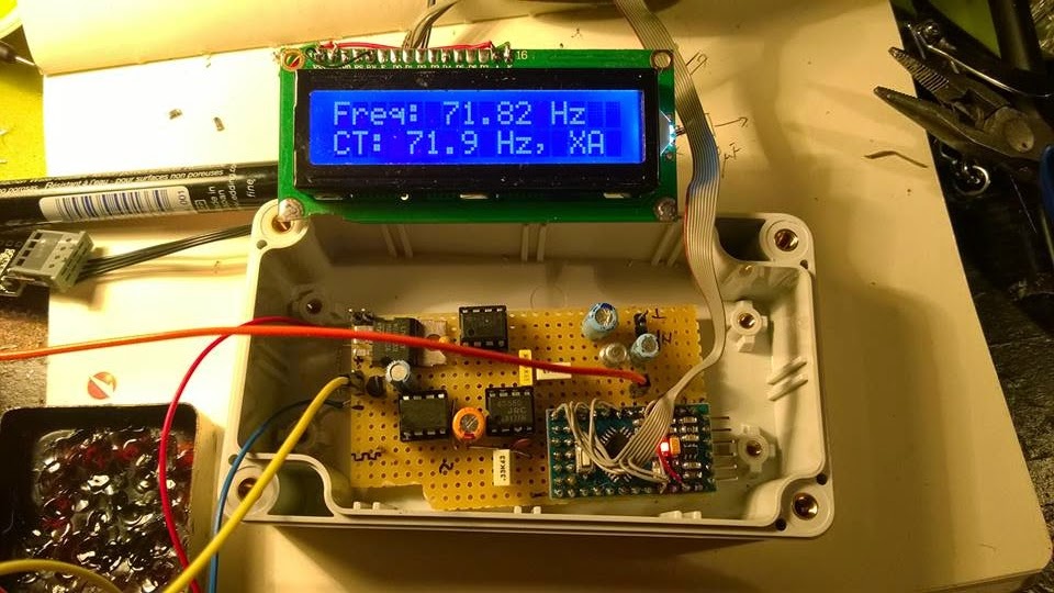
So I was turning to my Arduino trying to figure it out how to make it able to decode CTCSS in no more than 100 msec.
Finally, I did it by measuring the pulses between interrupts and find this method pretty nice and precise, at least for a crystal resonator driven Arduino.
*** Refinements of the initial code was further made by Jean-Jacques
ON7EQ and Paul ON4ADI. Please, read to the end.
Here is the code, just copy/paste it in the Arduino IDE: // Frequency counter sketch, for measuring frequencies low enough to execute an interrupt for each cycle // Connect the frequency source to the INT0 pin (digital pin 2 on an Arduino Uno) // By Adrian, YO3HJV // This work is released to Public Domain // First published on January, 18th 2015 on // http://yo3hjv.blogspot.ro/2015/01/ctcss-decoder-with-arduino.html // This code can be used for free but I will appreciate if you mention the author. // 73 de Adrian, YO3HJV
#include #include / *May be uncomment for standard Arduino LCD library. I am using a weird library here... */ LiquidCrystal lcd(8, 9, 4, 5, 6, 7); // set for my configuration. Let PIN2 to be the input for the signal. volatile unsigned long timpPrimImpuls; volatile unsigned long timpUltimImpuls; volatile unsigned long numImpuls; void setup() { //Serial.begin(19200); // print for debugging. Uncomment if necessary lcd.begin(16, 2); } // Measure the frequency over the specified sample time in milliseconds, returning the frequency in Hz float readFrequency(unsigned int sampleTime) { numImpuls = 0; // start a new reading attachInterrupt(0, counter, RISING); // enable the interrupt delay(sampleTime); detachInterrupt(0); return (numImpuls < 3) ? 0 : (996500.0 * (float)(numImpuls - 2))/(float)(timpUltimImpuls - timpPrimImpuls); } // NOTE: 996500.0 is the value find by me. The theoretic value is "1000000000.0" // Start with this value and check the precision against a good frequency meter. void loop() { float freq = readFrequency(100); lcd.setCursor(0, 0); lcd.print("Freq: "); lcd.print (freq); lcd.print(" "); lcd.print("Hz "); lcd.setCursor (0, 1); // Too low but over 10 Hz if ((freq > 10) && (freq < 65.8)) { lcd.print(" TOO LOW "); //DO SOMETHING } else if ((freq > 66.00) && (freq < 68.00)) { lcd.print("CT: 67.0 Hz, XZ "); //DO SOMETHING } else if ((freq > 68.30) && (freq < 70.30)) { lcd.print("CT: 69.3 Hz, WZ "); //DO SOMETHING } else if ((freq > 70.90) && (freq < 72.90)) { lcd.print("CT: 71.9 Hz, XA "); //DO SOMETHING } else if ((freq > 73.40) && (freq < 75.40)) { lcd.print("CT: 74.4 Hz, WA "); //DO SOMETHING } else if ((freq > 76.00) && (freq < 78.00)) { lcd.print("CT: 77.0 Hz, XB "); //DO SOMETHING } else if ((freq > 78.70) && (freq < 79.70)) { lcd.print("CT: 79.70 Hz, WB "); //DO SOMETHING } else if ((freq > 81.50) && (freq < 83.50)) { lcd.print("CT: 82.5 Hz, YZ "); //DO SOMETHING } else if ((freq > 84.30) && (freq < 86.50)) { lcd.print("CT: 85.4 Hz, YA "); //DO SOMETHING } else if ((freq > 87.40) && (freq < 89.60)) { lcd.print("CT: 88.5 Hz, YB "); //DO SOMETHING } else if ((freq > 90.40) && (freq < 92.60)) { lcd.print("CT: 91.5 Hz, ZZ "); //DO SOMETHING } else if ((freq > 93.7) && (freq < 95.90)) { lcd.print("CT: 94.8 Hz, ZA "); //DO SOMETHING } else if ((freq > 96.30) && (freq < 98.5)) { lcd.print("CT: 97.4 Hz, ZB "); //DO SOMETHING } else if ((freq > 99.00) && (freq < 101.00)) { lcd.print("CT: 100.0 Hz, 1Z "); //DO SOMETHING } else if ((freq > 102.40) && (freq < 104.60)) { lcd.print("CT: 103.5 Hz, 1A "); //DO SOMETHING } else if ((freq > 106.10) && (freq < 108.30)) { lcd.print("CT: 107.2 Hz, 1B "); //DO SOMETHING } else if ((freq > 109.80) && (freq < 112.00)) { lcd.print("CT: 110.9 Hz, 2Z "); //DO SOMETHING } else if ((freq > 113.60) && (freq < 116.00)) { lcd.print("CT: 114.8 Hz, 2A "); //DO SOMETHING } else if ((freq > 117.60) && (freq < 119.90)) { lcd.print("CT: 118.8 Hz, 2B "); //DO SOMETHING } else if ((freq > 122.00) && (freq < 124.00)) { lcd.print("CT: 123.0 Hz, 3Z "); //DO SOMETHING } else if ((freq > 126.20) && (freq < 128.40)) { lcd.print("CT: 127.3 Hz, 3A "); } else if ((freq > 130.40) && (freq < 133.00)) { lcd.print("CT: 131.8 Hz, 3B "); } else if ((freq > 135.00) && (freq < 138.00)) { lcd.print("CT: 136.5 Hz, 4Z "); //DO SOMETHING } else if ((freq > 140.00) && (freq < 142.80)) { lcd.print("CT: 141.3 Hz, 4A "); //DO SOMETHING } else if ((freq > 145.00) && (freq < 147.80)) { lcd.print("CT: 146.2 Hz, 4B "); //DO SOMETHING } else if ((freq > 150.00) && (freq < 152.80)) { lcd.print("CT: 151.4 Hz, 5Z "); //DO SOMETHING } else if ((freq > 156.00) && (freq < 158.80)) { lcd.print("CT: 157.7 Hz, 5A "); //DO SOMETHING } // NON-STANDARD else if ((freq > 159.00) && (freq < 161.00)) { lcd.print("CT: 159.8 Hz, -- "); //DO SOMETHING } else if ((freq > 161.00) && (freq < 163.50)) { lcd.print("CT: 162.2 Hz, 5B "); //DO SOMETHING } // NON-STANDARD else if ((freq > 164.00) && (freq < 166.30)) { lcd.print("CT: 165.5 Hz, -- "); //DO SOMETHING } else if ((freq > 166.60) && (freq < 169.00)) { lcd.print("CT: 167.9 Hz, 6Z "); //DO SOMETHING } // NON-STANDARD else if ((freq > 170.00) && (freq < 172.40)) { lcd.print("CT: 171.3 Hz, -- "); //DO SOMETHING } else if ((freq > 172.60) && (freq < 175.00)) { lcd.print("CT: 173.8 Hz, 6A "); //DO SOMETHING } //NON-STANDARD else if ((freq > 176.00) && (freq < 178.50)) { lcd.print("CT: 177.3 Hz, -- "); //DO SOMETHING } else if ((freq > 178.6) && (freq < 181.00)) { lcd.print("CT: 179.9 Hz, 6Z "); //DO SOMETHING } //NON-STANDARD else if ((freq > 182.00) && (freq < 184.80)) { lcd.print("CT: 183.5 Hz, -- "); //DO SOMETHING } else if ((freq > 185.00) && (freq < 187.50)) { lcd.print("CT: 186.2 Hz, 7Z "); //DO SOMETHING } //NON-STANRDARD else if ((freq > 188.40) && (freq < 191.30)) { lcd.print("CT: 189.9 Hz, -- "); //DO SOMETHING } else if ((freq > 191.00) && (freq < 194.00)) { lcd.print("CT: 192.8 Hz, 7A "); //DO SOMETHING } //NON-STANDARD else if ((freq > 195.40) && (freq < 198.00)) { lcd.print("CT: 196.6 Hz, -- "); //DO SOMETHING } //NON-STANDARD else if ((freq > 198.30) && (freq < 201.00)) { lcd.print("CT: 199.5 Hz, -- "); //DO SOMETHING } else if ((freq > 202.00) && (freq < 204.00)) { lcd.print("CT: 203.5 Hz, M1 "); //DO SOMETHING } else if ((freq > 205.00) && (freq < 208.00)) { lcd.print("CT: 206.5 Hz, 8Z "); //DO SOMETHING } else if ((freq > 209) && (freq < 212.00)) { lcd.print("CT: 210.7 Hz, M2 "); //DO SOMETHING } else if ((freq > 217.00) && (freq < 219.30)) { lcd.print("CT: 218.1 Hz, M3 "); } else if ((freq > 224.00) && (freq < 227.00)) { lcd.print("CT: 225.7 Hz, M4 "); } else if ((freq > 227.60) && (freq < 231.30)) { lcd.print("CT: 229.1 Hz, 9Z "); //DO SOMETHING } else if ((freq > 231.70) && (freq < 235.00)) { lcd.print("CT: 233.6 Hz, -- "); //DO SOMETHING } else if ((freq > 239.60) && (freq < 243.00)) { lcd.print("CT: 241.8 Hz, M6 "); //DO SOMETHING } else if ((freq > 248.00) && (freq < 252.00)) { lcd.print("CT: 250.3 Hz, M7 "); //DO SOMETHING } else if ((freq > 252.70) && (freq < 256.80)) { lcd.print("CT: 254.1 Hz, 0Z "); //DO SOMETHING } else if (freq > 256.80) { lcd.print(" TOO HIGH "); //DO SOMETHING } else { lcd.setCursor (0, 1); lcd.print(" NOISE "); // or, comment the line above and // uncomment the line below for an empty LCD line // lcd.print(" "); } delay(50); // lcd.clear(); //Not necessary. uncomment but will flicker! } //END OF LOOP void counter() { unsigned long now = micros(); if (numImpuls == 1) { timpPrimImpuls = now; } else { timpUltimImpuls = now; } ++numImpuls; }
After fine tuning the code, the second issue was to make the Arduino read from real life signals, a.k.a from the discriminator (FM detector).
But there, unfortunately, there is also "noise" above 300 Hz from the voice and the Arduino will tend to detect it too, asuming that we have a 5Vpp signal on pin 2 of the UNO board.
Therefore, a preamplifier and a Low Pass Filter to cut all the frequencies below* above 260 Hz with at least 12db/octave.
I will not bother you with more than necessary details, I post the schematics here and if someone has questions i will answer.
73 de Adrian YO3HJV
A "Later Edit" is a must!
After some emails with Carlo IU1DOR found some mistakes in the schematics. One is about the parallel diodes at U3a which are drawn as conductive in one sense; must be corrected as anti-parallel diodes.
The second one is R10 which is not in series with that diodes.
Here is the original part from Motorola GM300 schematics:
Anyway, Carlo kindly give me the permission to post here the PCB layout for the filter (TNX!):
The code is available on GITHUB. *-TNX IU1DOR for correction!
LATER EDIT (15 feb. 2016)
I recently received a e-mail from Jean-Jacques
ON7EQ who pointed me to an upgrade to this project.
The upgrade was made possible by the work of Paul ON4ADI who refine the code and added a necessary software filter to make the CTCSS Arduino decoder able to withstand to real world conditions. The project of the new CTCSS decoder can be seen here.
I finished a complex project, a mini Meteo Station based on Arduino Nano.
On a 4x20 I2C LCD I can see the date, time, inside and outside temperature, relative humidity and air pressure (in hPa).
Main features are:
-Low footprint -Precise Date and Time with a DS1307 RTC circuit
-Humidity with a DHT-11 sensor
-Baro pressure and interior temperature with a BMP-085
-External temperature with a DS-18B20
-Low power (40 mA from one Li-Ion cell with a DC-DC converter with LCD Backlight on, 30 mA).
-LCD Backlight on demand by push button
Took me about 2 days but I made it!
I intend to make some averages and to compare the pressure over an variable inteval tohave a weather prediction.
Here is the code:
/*
Meteo station with Arduino Nano by Adrian, YO3HJV http://yo3hjv.blogspot.com
-- LCD on I2C -- Barometer and temperature sensor BMP-085 on I2C -- Humidity sensor DHT-11 on pin D3 -- Dallas DS-18B20 temperature sensor on OneWire, pin D2 -- Backlight Push button on pin A3
if (val == LOW) { lcd.backlight(); // Backlight ON and... sens(); // ... execute "sens" }
else // if not ..., { lcd.noBacklight(); // Backlight OFF and... sens(); // ...execute "sens" } }
void sens() // Main function {
tmElements_t tm; //DS1307 RTC sensors.requestTemperatures(); // Send the command to get ext temperature tempext = sensors.getTempCByIndex(0);
//BARO + TEMP PE I2C // we read all the values from barometric sensor but use only temperature and pressure // we might calculate Dew point! temperature = myBarometer.bmp085GetTemperature(myBarometer.bmp085ReadUT()); //Get the temperature, bmp085ReadUT MUST be called first pressure = myBarometer.bmp085GetPressure(myBarometer.bmp085ReadUP()); //Get the temperature altitude = myBarometer.calcAltitude(pressure); //Uncompensated caculation - in Meters atm = pressure / 101325;
//Hygro sensor DHT-11 int chk = DHT11.read(DHT11PIN);
lcd.setCursor(0, 2); lcd.print("In: "); lcd.print(temperature); // we can use [lcd.print(int(temperature))] for value without decimals; lcd.print(" *C "); // otherwise, temp is with two decimals
lcd.setCursor(0, 3); lcd.print("Ex: "); lcd.print(tempext); // the same as above ... lcd.print(" *C ");
A few days ago I was contemplating a little device from a hobby store. It was a smart power gauge meter for tracking the charge and discharge of a battery.
I was wondering if I cannot do it by myself with a Arduino Uno board and some current sensor.
As I'm not a code-freak dude, I did a little research and found a nice start for my project, right here.
I do have a ACS-712 for 5 Amps and also for 30 Amps.
I decided to start with the little one as my project is designated for my portable HF backpack based on ICOM IC-703.
As the Arduino ADC input cannot accept more than 5V, a voltage divider has to be used.
Is the classic one, in wich I used a 10 kOhm from A4 to ground and a 100 kOhm from A4 to the probe. I used SMD resistors but after I measured the ratio I found that the real ratio is not 10 to 1 but somewhere around 10.93:1.
It is important as this ratio will be used to calculate the voltage into the Arduino code.
I modified the code from Instructables because it had some major measurement errors inside as it was written for ACS715 and I do have some problems here with the libraries since I tried to do some tests with I2C LCDs... Also, I found a lot of discussions about how that code is not working properly.
So, below is my version of the code of the Energy meter with ACS-712-05T.
The code is heavily commented so, I believe is easy to understand what is about.
/* This sketch describes how to connect a ACS712 - Bidirectional Current Sense Carrier to the Arduino, and read current flowing through the sensor.
*/
LiquidCrystal lcd(8, 9, 4, 5, 6, 7); // Easy to connect the LCD Shield
/*
Vcc on carrier board to Arduino +5v GND on carrier board to Arduino GND OUT on carrier board to Arduino A0
Insert the power lugs into the loads positive lead circuit, arrow on carrier board points to load, other lug connects to power supply positive
*/
int batMonPin = A4; // input pin for the voltage divider int batVal = 0; // variable for the A/D value float pinVoltage = 0; // variable to hold the calculated voltage float batteryVoltage = 0;
int analogInPin = A0; // Analog input pin that the carrier board OUT is connected to int sensorValue = 0; // value read from the carrier board int outputValue = 0; // output in milliamps unsigned long msec = 0; float time = 0.0; int sample = 0; float totalCharge = 0.0; float averageAmps = 0.0; float ampSeconds = 0.0; float ampHours = 0.0; float wattHours = 0.0; float amps = 0.0;
void setup() { // initialize serial communications at 9600 bps: Serial.begin(9600); lcd.begin(20, 4); }
void loop()
{
int sampleBVal = 0; int avgBVal = 0; int sampleAmpVal = 0; int avgSAV = 0;
for (int x = 0; x < 20; x++) // run through loop 20x
{ // read the analog in value: sensorValue = analogRead(analogInPin); sampleAmpVal = sampleAmpVal + sensorValue; // add samples together
batVal = analogRead(batMonPin); // read the voltage on the divider sampleBVal = sampleBVal + batVal; // add samples together
delay (10); // let ADC settle before next sample
}
avgSAV = sampleAmpVal / 20;
// convert to milli amps outputValue = (((long)avgSAV * 4980 / 1024) - 2485 ) * 1000 / 130;
/* Modified by Adrian YO3HJV for real life ACS712-05A
Sensor outputs about 2.485 V at rest. Analog read produces a value of 0-1023, equating to 0v to 5v. "((long)sensorValue * 5000 / 1024)" is the voltage on the sensor's output in millivolts. "5000"mV is ideal value, my board has 4.985 V measured with a precision Voltmeter Therefore, we have a 2485mv offset to subtract. The unit produces 185 mv per amp of current, so divide by 0.185 to convert mV to mA. The documentation said that the ACS has 185mV/Amp but I measured 130 mV/ Amp.
*/
avgBVal = sampleBVal / 20; //divide by 20 (number of samples) to get a steady reading
pinVoltage = (avgBVal * 5.0) / 1024;
// Calculate the voltage on the A/D pin /* A reading of 1 for the A/D = 0.0048mV if we multiply the A/D reading by 0.00488 then we get the voltage on the pin. It is a good practice to measure the Vcc with a good voltmeter and to adjust the 5.0 V to the measured value. Also, depending on wiring and where voltage is being read, under heavy loads voltage displayed can be well under voltage at supply. monitor at load or supply and decide. */
batteryVoltage = pinVoltage * 10.93; /* 10.93 is the voltage divider ratio measured with a voltmeter. First, measure the input voltage (ex. 12V) Then, measure the voltage at pin A4 (V input). Then make the ratio between and write it here. */
//Here we print the data output to serial port. //Usefull for some data logging onto PC Serial.print("Volts = " ); Serial.print(batteryVoltage); Serial.print("\t Current (amps) = "); Serial.print(amps); Serial.print("\t Power (Watts) = "); Serial.print(watts);
 A few days ago, Tony, YO3FXF came to our laboratory with a very nice looking Kenwood R-5000 Communications Receiver.


