24 April 2024

Expansion board for ESP32 D1Mini


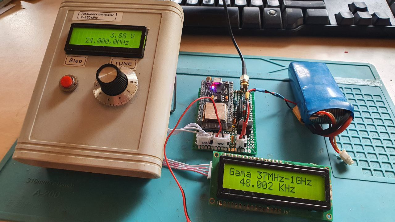
Well, after testing a lot of ESP32 development boards, I found that the little ESP32 D1 Mini is an excellent one.


First of all, it is very fast when programming!

Second, you don't have to fuss around with pressing BOOT, EN/RST or other complicated procedures!

Third, never, but never the programming stopped due to communication errors (like a lot of DevKit boards).

The single inconvenient I can found, and is a big one, is the dual rows of pins!

They are hard to access, I always misread the labels because they are very crammed and I found stupid to have them on the back of the board, but this is, of course, because there is no space on the upper side.

Anyway, you get the ideea: very good boards but pretty hard to use Dupont wires to test various hardware with them.

So, I was looking to an expansion board for Arduino Nano and asked myself if I can find a similar board for D1 Mini! Back in the old days when i start with Arduino (and Nano was a cheap thing) this expansion board was a gem and help me with a lot of projects....


So, I searched for a similar one but all that I found were little boards with some sh$%# on them, none being what I was really needed!

But then, I asked myself, "why not MAKING one"?

First step is to make a PLAN! What are my expectations? How do I mostly use this dev boards? What accessories I often use? 

So, the requirements were written on a paper:

-Power supply from a various sources; both from USB and from external 6-20V.

-Multiple I2C configured to use I2C LCD with SCL, SDA, +, GND.

-I2C for 3V3 and 5V accessories.

-Every GPIO to have it's 3V3 and GND pins near for easy wiring.

-If the board is external powered, the regulated voltages to be available for other accessories.

-Multiple SPI.

-Accessible UART for ... things...

Using EasyEDA I made the schematic:

... and while waiting for the boards ordered in China, I also ordered the components.


Well, yeah, a close inspection will reveal that I made a mistake with the coaxial power Jack... I wired the wrong pin to Vcc :-( but the cutter fixed the little annoyance.


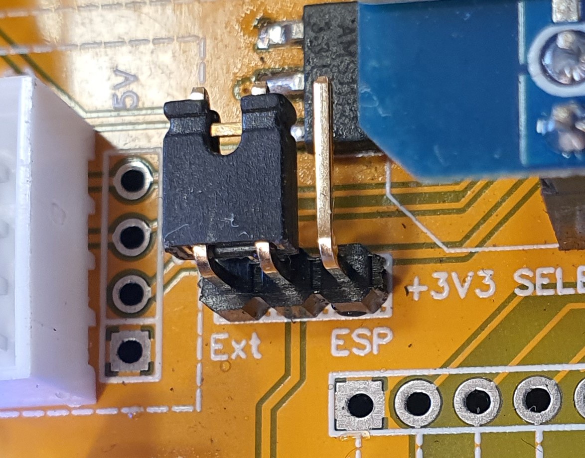
The 3V3 can be selected from the external power supply or from the ESP regulator:


I have two 3V3 I2C and two 5V I2C. Yes, i know the best practice is to have level translators but a 220 Ohm on each SDA and SCL will do the job very well...


3 SPI, one with the CS0 at GPIO5


UART and two regulated power outputs:


... and each GPIO have its GND and +3V3 near...


All files can be found on Github.


09 April 2024

ADC. Rezolutii si Volti

ADC-urile convertesc eșantioanele unui semnal analogic în valori digitale.

RezoluÈ›ia ADC-ului este numărul de biÈ›i pe care îl utilizează în vederea digitizării eÈ™antioanelor de intrare. 

Pentru un ADC pe n biÈ›i, numărul de niveluri digitale discrete care pot fi produse este 2n. 

Astfel, un digitizor pe 12 biÈ›i poate rezolva 212 sau 4096 niveluri. 

Cel mai puÈ›in semnificativ bit (lsb) reprezintă cel mai mic interval care poate fi detectat È™i, în cazul unui digitizor pe 12 biÈ›i, este 1/4096 sau 2,4 x 10⁻⁴. 

Pentru a converti lsb într-o tensiune, luăm intervalul de intrare al digitizorului și îl împărțim la doi, ridicat la rezoluția digitizorului.

27 March 2024

VFO Encoder selection for Xiegu G90

From time to time someone start searching for part number of the VFO encoder.

Here is a selection of part numbers for encoders without detent (no clicks) and with detents (like the original one).

A NOTE FROM  PA2HJK, received by e-mail:

Hello Adrian, 

Thank you for all the information about the Xiegu G90.  I used it to replace my VFO encoder but I had to reverse the outer connections  ( of the 3 pins side) of the encoder. The switch worked fine but the rotation was inversed. I have tried several encoders from Bourns and ALPS but they where all reversed.

Maybe you can add this information to your website to help other Hams.
 

73’s  Harm Jan  PA2HJK


An email exchange with Paul VE7NRI showed the same problem. 

A note based on IV3TEK Luca emails and practical experience:


On the left is the broken original encoder while in the right side is the Bourns replacement 
PEC11R-4120K-S0018.

While PEC11R-4120K-S0018 have knurled shaft, it is slightly longer than the original Chinese encoder as seend in the picture above.


Luca made a PVC disk to compensate for that:

If keeping the original knob is not mandatory, a flatted shaft will have the same lenght.

Thank you Luca for the detailed feedback! 


 A NOTE FROM ME:

When I searched for the proper replacement I assumed that Xiegu G90 use standard phase in it's rotary encoders and focused on dimensions and mechanichal criterias; never imagined that they are not delivering the same way. 

Therefore, it is necessary to cross the terminals (small pieces of wire) for the below encoders in order for it to function properly.

 Taken the above into account, you must cross the pins to match the rotation of the new encoder with the result of the VFO or to search for the cheap Chinese-made replacements.

To match the desire of the user, ICOM use a lever to "add" detents to some of their radios. When using in mobile, detents may be convenient while using it stationary, no detents might be the choice.

There are a lot of manufacturers that make cheap PC11 type encoder but the reliability is not very good; while they can be used in home-made projects, in the radio a more sturdy one is needed. 

Also, they might fail and most hams try to find a faster way to repair the radio than to send it back to China and wait a few months.

Therefore, here are a few options for those "brave hams" that will take the things into their hands and will repair the radio by themselves.

As a personal observation, with more than 18 pulses per revolution it is a pain to use a no detents encoder...


From BOURNS:


No detens:

PEC11R-4020K-S0018 with knurled shaft, 20mm lenght, no detents, momentary switch and 18 pulses per revolution.

PEC11R-4025F-S0018 with flatted shaft. From ALPS, EC11E, 20mm long flatted shaft (only) momentary switch.

With  detents:

PEC11R-4120K-S0018 - 20mm long shaft, knurled (4120F for flatted shaft), momentary switch.

PEC11R-4125K-S0018 - 25mm long shaft, knurled (4125F for flatted shaft), momentary switch.


From ALPS: 


No detents:

EC11E153440D with 15 pulses per revolution. Flatted shaft. 20mm long, momentary switch.

EC11E18344OC with 18 pulses per revolution. Flatted shaft. 20mm long, momentary switch.

With detents:

EC11E18244AU with 32 detents, 18 pulses per revolution. Flatted shaft. 20mm long, momentary switch.

EC11E15244B2  with 30 detents, 15 pulses per revolution. Flatted shaft. 20mm long, momentary switch.


Serrated (knurled). Please check the dimensions of the shaft for proper selection of the knob.


Without detent:

EC11G1574402 - 15 pulses per revolution, momentary switch.

With detent:

EC11G1564411 - 30 detents, 15 pulses per revolution, momentary switch.


For both producers I reccomend study their product selection datasheets which can be downloaded as pdf clicking on their names.

The pinout of the above encoders is compatible with the one in the radio.

I usually like to have longer shafts and cut them to my needs so, if you want a shorter one, just check the datasheets for the part number. 

Both manufacturers are producing compatible encoders for VFO, VOL and FUNCTION. 


23 March 2024

Simplyfying the code by using a tic-tac machine

Playing with Arduino and it's C++ I often use timed tasks.

Basically, in Arduino you can do things at specific interval either by adding delay() at some strategic points or using wellknown non-blocking code:

const unsigned long interval = 1000; // Interval for LED blink (in milliseconds)
unsigned long previousMillis = 0;    // Variable to store time since last LED update

int ledPin = 13; // Pin for the LED

void setup() {
                    pinMode(ledPin, OUTPUT); // Initialize LED pin as an output
  }

void loop() {

                  unsigned long currentMillis = millis(); // Get the current time

  // Check if it's time to update the LED
  if (currentMillis - previousMillis >= interval) {
                    previousMillis = currentMillis; // Save the last time LED was updated
                    digitalWrite(ledPin, !digitalRead(ledPin)); // Toggle the LED state
          }

      // Other non-blocking tasks can be added here
}
 
What if, the code need more than one timer?
Well, we  can use multiple timers like that!
While this is the simple and easy way, in a big code we start loosing track of what does what and if the code is big, each byte counts! Let's not forget that  each unsigned long type variable cost us 4 bytes of precious memory; each byte consists of 8 bits, and an unsigned long on Arduino is a 32-bit data type, so it occupies 4 bytes (32 bits / 8 bits per byte = 4 bytes).
I have a program in which I have to test multiple timers with multiple distinct intervals and the memory cost was huge.
So, I stayed and think and found a very elegant solution.
While I may reinvented the wheel, I think it is nice to share it with you!
It is all about making a single time measuring function and asign boolean variables to keep track of various things.
  unsigned long previousMillis_ONESECOND = 0; // Variable to store the last time the ONESECOND was flipped
  const unsigned long interval_ONESECOND = 1000; // Interval at which to flip the ONESECOND (in milliseconds)
    bool ONESECOND = false;

void loop(){
    updateONESECOND(); }

void updateONESECOND(){
          unsigned long currentMillis = millis(); // Get the current time
 
          // Check if it's time to flip ONESECOND
          if (currentMillis - previousMillis_ONESECOND >= interval_ONESECOND) {
            // Save the last time ONESECOND was flipped
            previousMillis_ONESECOND = currentMillis;

           // Flip ONESECOND
            ONESECOND = !ONESECOND;
      }
}
then, I have other functions that check various conditions AND bool.
For example, a function that blink a special character on a LCD: 
 
bool ProcessSTART = false;
 
void fLCD(){  // alternate symbol at a rate of one second while StartLog is activated
            if (ONESECOND && ProcessSTART){
                     printFN_Char();
                            }
                else {
                     printFP_Char();
                }
}

the other bool ProcessSART is flipped in other part of the program.
In other functions you can count the number of seconds using this tic-tac function and get other intervals derived from it, using less bytes in a simple arithmetic function.
It's like using an external time generator for all the functions in the code.

06 March 2024

Frecventmetru 0-1GHz cu ESP32

Uneori am avut nevoie de un frecventmetru cu precizie ridicata pentru verificarea unor montaje facute acasa.

Cum spatiul pe masa de lucru este limitat, nevoia m-a impins sa caut un echipament miniaturizat.

Sigur ca exista produse industriale dar, unde mai este placerea de a construi ceva?

Un frecventmetru cu ESP32 ar rezolva problema, mai ales ca, teoretic, poate masura frecvente pana la 40 MHz.

Cu ajutorul unui prescaler, gama de frecvente masurate poate fi extinsa, cu mentinerea unei precizii satisfacatoare in pseudo-laboratorul de acasa.


Schema electrica (click pentru o versiune marita a imaginii):

Cateva precizari:

-Nivelul maxim al semnalului la borne este de 10dbm, adica 10mW/50 Ohm.

-Montajul poate fi simplificat prin utilizarea doar a placii ESP32 si a condensatorului de decuplare la intrarea de semnal dar recomand, totusi, utilizarea unui divizor pentru a proteja intrarea de semnalele mai mari de 3V varf la varf.

Pentru a obtine fisierele .bin necesare scrierii programului, va rog sa ma contactati prin email


Most viewed posts in last 30 days